Jessica Sanders (13-ERD-047)
Abstract
One of the most challenging areas for numerical simulation in solid mechanics is that of the failure and post-failure behavior of engineering materials. In this work, we developed a computational framework for the prediction of fracture and fragmentation of engineering structures. We implemented a prototype of the method in DYNA3D, a finite-element software package for structural dynamics. The fracture method itself is a way to split a continuous finite-element domain into disconnected parts based on the appearance of cracks as predicted by a material model. The method is based on the addition of degrees of freedom in the vicinity of a crack. Several test problems were developed to demonstrate the accuracy and robustness of the method for brittle failure calculations. Two of these test problems are described in detail.
Background and Research Objectives
The fracture of structural materials has many national security applications, from stockpile stewardship science to penetrating munitions. Predicting structural failure is an important step in the development of many engineering products including pipes, pressure vessels, automobiles, and aerospace structures. In many cases, modeling a structure to the point of gross mechanical failure (and not beyond) has been sufficient to yield design parameters. As engineering simulation tools increase in sophistication, we can apply them to harder problems. Thus, there has been a great expansion of development in the post-failure analysis of structures through computational means. There are now many options for simulating the behavior of cracks, and even branching cracks, as they propagate through materials. Notable computational frameworks include damage-based constitutive models (potentially with element erosion), the cohesive zones of Camacho and Ortiz, phase field methods that go back to Francfort and Marigo, strong discontinuity methods as developed by Linder and Armero, adaptive mesh refinement, and the extended finite-element method of Dolbow et al.1–4
For this work, we were interested not only in modeling structures that fail under dynamic loading, but also post-fracture behavior, material separation, possible fragmentation, and fragment behavior. An example problem might be the explosive fragmentation of a structure, followed by collateral damage to other nearby structures from material fragments. To this end, we looked for a numerical method that could describe the topological changes that occur with fracture and that would satisfy the following criteria:
- Flexibility to multiple material descriptions of failure, including brittle and ductile models
- Conservation of energy and momentum
- A numerical description of fracture surfaces that allows for complete kinematic separation, and the possibility that fracture surfaces may be involved in additional mechanics (recontact, etc.)
- The ability to describe and track a very large amount of interconnecting cracks that may occur in fragmentation
- Freedom from mesh dependency associated with either strain softening or the artificial constraint of the crack path
- Computational efficiency
This was a very ambitious set of criteria, as is reflected in the many decades of academic research devoted to the area. To meet these criteria, we focused on a phantom node approach to fracture propagation. In this approach, crack initiation and propagation are based on the underlying material laws and determined on an element-by-element basis. This is commonly the approach for enhanced strain methods and has been shown to be very robust. When material failure causes a crack surface to appear, that surface is represented locally and described independently in each element via element duplication. There is no need of a global algorithm to track cracks and no limitation of the amount of cracks that can nucleate or propagate in a mesh.
We implemented and tested the framework in DYNA3D, the Laboratory’s explicit structural dynamics finite-element software. One of the cornerstones of the method—the local, physics-based approach to failure—also represented the greatest algorithmic challenge, allowing no guarantee of a crack field that is easy to represent. As a complement to the algorithm itself, we produced a test suite, including verification problems, and models of physical systems based on known fracture experiments, which are discussed below.
Scientific Approach and Accomplishments
Notation and Continuum Problem
We considered the dynamic motion of a body in R3 with initial configuration Ω0 and experiencing time-dependent body and surface loads. The current configuration, Ω, may be topologically distinct from Ω0 due to material fracture and separation.Material Considerations
Given a state at t = n, we wished to predict whether the onset of material failure would occur, and if so, to dissipate the appropriate energy based on the formation of cracks and then change the domain topology accordingly. We relied on a failure model based on material stress to indicate the onset and geometry of failure.
A computational description of fracture has to account for the energy consumed by the formation of new cracks. The two common techniques for introducing this dissipation into a finite-element simulation are damage models and cohesive zones. Either may be accommodated by our underlying numerical method. Our numerical demonstrations relied on a material damage model that was already developed for DYNA3D.
In the subsequent numerical experiments, we applied the brittle failure model of Govindjee et al.5 The material behaved elastically until the onset of damage, which occurred when the first principle stress reached the material tensile strength. A crack orientation was identified normal to the principal stress direction. As loading advances, the material strength was degraded through evolution of the material compliance tensor. When the material strength dropped to a particular threshold, we considered that the element had failed.
Crack Boundary Reconstruction
At t = 0, we superposed a standard finite-element mesh, Ωh, of solid hexahedral elements on the reference configuration. Through a standard set of finite-element arguments we obtained the set of matrix equations
Mü + F(u) − P(u,t) = 0,
where M is a mass matrix, F is the internal force, and P(u,t) is the body force and external load vector. We did a row sum on M to achieve a diagonal mass matrix and used the central difference method to integrate the equations in time.
As the equations were advanced in time, discrete elements could degrade and fail. That event triggered an algorithm (described below) for introducing cracks into the interior of the mesh, which involves adding degrees of freedom in the vicinity of the crack location. Thus, the length of the solution vectors u and ü were subject to increase. Because the solution scheme is explicit, the computational cost of the additional degrees of freedom was not large.
Unlike many extended finite-element method approaches, ours did not employ a global algorithm for crack propagation, nor did we enforce continuity of the cracks within a mesh. Interfaces were placed in failed elements with the orientation given by the material failure model. As an initial guess, interfaces were placed at element centers. After initial placement, a moving least-squares method adjusted the crack location within elements to a closer approximation of a continuous surface, while maintaining their original orientation.
Remeshing
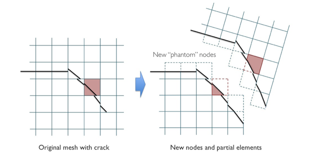
We followed the arguments of Hansbo and Hansbo, wherein doubling the nodes in an element crossed by an interface gives the appropriate amount of degrees of freedom to capture the new kinematics.6 At the time of creation, the new degrees of freedom were co-located with the original element nodes and inherited their current nodal velocities. We used the term “phantom nodes” to refer to the nodes that supported a partial element but that were located outside of the element’s material region. The new partial elements had a material boundary interior to the element nodal basis.
Assuming the cracks aggregate properly, the phantom nodes uncoupled the mesh on either side of a global fracture as in a standard extended finite-element method (Figure 1).
Strain, Mass, and Stable Time Step
Newly created elements that were only partially filled with material required special calculations for internal and inertial forces. Internal forces could be integrated in the standard way, but restricted to the partial area. Element mass matrices were computed using partial-element volumes with all mass lumped and distributed equally to the underlying nodes. This mass-lumping strategy was introduced in Menouillard et al., where it is shown to minimize the effect of the interface location on the critical time step, even when the volume of the material is much smaller than volume of the underlying basis.7
Element Connectivity
Taken in isolation, partial elements were free to separate, as in Figure 1. However, in a real simulation, cracks may not align in a predictable way. This leads to several potential pitfalls of the approach and illuminates why most numerical methods force cracks to propagate continuously through a mesh. When adjacent elements experience cracking with radically different normal direction vectors, there may be no way to adjust these interface positions in the elements to properly adjoin, and partial elements may be artificially blocked from separating. This may occur when the problem is spatially not well resolved, or when some bifurcation is occurring, such as crack branching. To help alleviate this difficulty, we allowed judicious failure of partial elements—this issue remains the defining challenge for future efforts.
Numerical Demonstrations
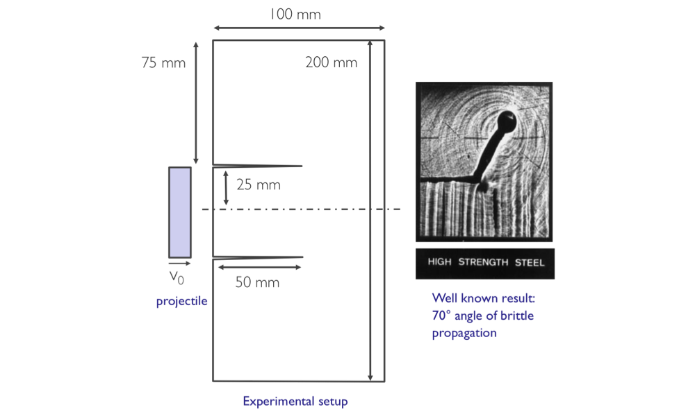
We demonstrated the framework in this work though benchmark numerical simulations of brittle fracture scenarios. Two are detailed here. The first scenario was a classic experiment on brittle steel, referred to as the Kalthoof experiment.8 In this scenario, a hard projectile impacts the edge of a thin notched plate of material (see Figure 2). The result is a shear wave that propagates through the material and extends the crack.
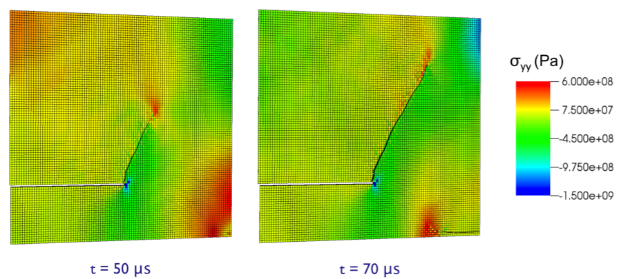
We modeled the problem in half symmetry. The material properties are of high-strength steel: E = 200GPa, ν = 0.25, failure strength σf = 2GPa, and fracture surface energy Gc = 200kJ/m2. The impact loading is simulated with an applied velocity pulse. Though the physics of the problem are planar, the finite-element meshes used were three dimensional, with one, two, and four elements through the thickness. Results for a representative mesh are given in Figure 3.
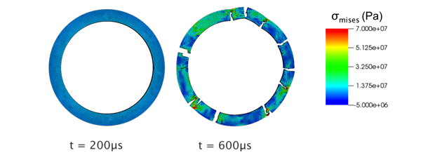
The second demonstration problem was a simulation of a spinning disk of material. Numerical setup and parameters are given in Figure 4. The spinning disk problem is commonly used to study the fragmentation behavior of various materials. Greater values of angular velocity lead to a finer distribution of fragments. Representative results are given in Figure 5.
Impact on Mission
Representing fracture and fragmentation in finite-element models is supportive of the Laboratory’s core competency in high-performance computing, simulation, and data science. The fracture of structural materials is relevant to many national security applications. Defense applications include prediction of structural survivability for transport security and blast protection of armored vehicles, as well as bullet impact on propellants, impact-driven fragmentation in high explosives, and structural spall during high-pressure deflagration events. The work herein helps to keep the solid mechanics models in DYNA3D competitive with other laboratories in the DOE complex and industry.
Conclusion
This work represents the development of a computational framework for prediction of fracture and fragmentation of brittle materials and structures. Engineers working on large systems have an interest in accurately predicting structural failure. If and when the prototype is polished into a fully functional user capability, it will be integrated into the engineering tools that are used to support stockpile stewardship for increasing challenging scenarios. The current instantiation in DYNA3D is a prototype. We have identified several improvements that target the performance of large three-dimensional problems as well as problems with complex crack topologies. In the method as developed, elements can crack from edge to edge, and partial elements can be deleted when warped or when they appear to block the progress of branching patterns. This approach could be extended to include a capability for elements to be divided into multiple partial elements. Doing so would provide more flexibility and reduce warping and snagging of element pieces. There may be opportunities to collaborate with the academic community on additional research. For example, there is now a great deal of interest in the prediction of ductile tearing. Our method may be an excellent framework for testing the accuracy of various ductile models. Overall, the project established a solid base that could be used as a springboard for future research.
References
- Camacho, G. T., and M. Ortiz, “Computational modeling of impact damage in brittle materials.” Int. J. Solid. Struct. 33, 2899 (1996).
- Francfort, G. T., and J. J. Marigo, “Revisiting brittle fracture as an energy minimization problem.” J. Mech. Phys. Solid. 46, 1319 (1998).
- Linder, C., and A. Armero, “Finite elements with embedded strong discontinuities for the modeling of failure in solids.” Int. J. Numer. Meth. Eng. 72, 1391 (2007).
- Dolbow, J., N. Moës, and T. Belytschko, “An extended finite element method for modeling crack growth with frictional contact.” Comput. Meth. Appl. Mech. Eng. 190, 6825 (2001).
- Govindjee, S., G. Kay, and J. C. Simo, “Anisotropic modelling and numerical simulation of brittle damage in concrete.” Int. J. Numer. Meth. Eng. 38, 3611 (1995).
- Hansbo, A., and P. Hansbo, “An unfitted method for the simulation of strong and weak discontinuities in solid mechanics.” Comput. Meth. Appl. Mech. Eng. 193, 3523 (2003).
- Menouillard, T., et al., “Mass lumping strategies for x-fem explicit dynamics: Application to crack propagation.” Int. J. Numer. Meth. Eng. 74, 447 (2007).
- Kalthoff, J. F., and S. Winkler, “Failure mode transition at high rates of shear loading.” Impact loading and dynamic behavior of materials, vol. 1, Fraunhofer IFAM, Bremen, Germany (1987).
Publications and Presentations
- Sanders, J., and M. Puso, A local phantom node approach for dynamic fragmentation. IX Intl. Conf. Computational Modeling of Fracture and Failure of Materials and Structures, Cachan, France, June 3–5, 2015. LLNL-ABS-666694.
- Sanders, J., and M. Puso, A local phantom node approach for engineering fracture and fragmentation. (2015). LLNL-PRES-671584.
- Sanders, J. D., and M. A. Puso, A phantom node approach to dynamic crack propagation. 12th U.S. Natl. Congress on Computational Mechanics, Raleigh, NC, July 22–25, 2013. LLNL-PRES-641179.


