Andrea Schmidt (15-ERD-034)
Abstract
Our project team designed, constructed, and commissioned a compact dense plasma focus device as a pulsed-neutron source. This was the first such device using kinetic plasma simulations to iteratively prototype the design. The simulations were performed using two fully kinetic particle-in-cell codes, LSP and Chicago (Thoma et al. 2017), to simulate the dense-plasma-focus geometry and driver from the experiment. Hundreds of simulations were performed to inform the pulsed-power capacitor bank size, the length and shape of the anode, the operating voltage, and the fill pressure in the device. The dense-plasma focus capacitor bank was built with a lower capacitance and higher voltage than typical devices to achieve higher currents, initially causing plasma restrikes that diverted current from the pinch region. The device reliably produced neutrons without arcing because a novel anode shape was developed to mitigate the arcing associated with the device's compact size. The prototype was purposefully oversized to allow for charging capacitors well below their rated voltage, as well as to accommodate pressure safety regulations present in a research-and-development environment. However, the target-end of the dense-plasma focus device was kept small: the anode is 1.5 cm in diameter and 1 cm in length, while the size of the plasma sheath is 2 cm in diameter by 2-cm long.
Background and Research Objectives
Compact neutron sources have a wide variety of applications in global security and stockpile stewardship. Radiation-generating devices (RGDs) can replace dangerous radiological materials currently deployed in commercial and industrial applications, such as petroleum well logging and mining. Using pulsed detection techniques, portable RGDs can aid in the detection of special nuclear materials (SNM), high explosives, and drugs. The dense plasma focus (DPF) is a plasma-based RGD that creates a very short pulse (30–100 ns) of neutrons suitable for these applications with an attractive size, weight, power, and cost requirements. DPFs rely on plasma instabilities to accelerate ions to energy levels high enough to fuse and create neutrons. Lawrence Livermore National Laboratory has recently used a kinetic, particle-in-cell (PIC) code to capture DPF dynamics and neutron yields for the first time (Schmidt et al. 2012 and 2014). The simulations can be run in parallel on computer clusters to investigate scaling machine parameters at a fraction of the cost and time it would take in the laboratory. This affords the opportunity to use parallel simulations to iteratively optimize a compact laboratory DPF to maximize neutron yields. There is no consensus in the DPF community about the details of the acceleration processes inside DPFs, but our project developed an understanding and intuition about these mechanisms using predictive simulations.
Our project team developed a compact DPF for neutron production using parallel simulation scalings to inform the design decision in the laboratory. A compact DPF was simulated to inform the anode shape and pulsed power driver. A prototype DPF was constructed in the laboratory with diagnostic access to make measurements to compare to the simulations. Throughout the prototyping process, we fed the information from the experiments back into the simulations, ran new simulations, and developed new designs for the laboratory DPF.
Scientific Approach and Accomplishments
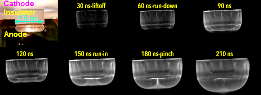
A DPF is a coaxial device that produces a cylindrically symmetric plasma sheath that merges, then "pinches" to produce an ion beam. A capacitor bank is discharged across a coaxial anode–cathode gap that is surrounded by low-pressure fill gas. A plasma is formed that lifts off the insulator, runs down the anode, then runs in to a pinch. During the pinch phase, instabilities in the plasma create large axial electric fields which accelerate ions in the plasma sheath to very high energies ( > 1 MeV). These distinct phases are captured in fast-framing camera images (Figure 1). The ions interact with the extremely dense pinch plasma as well as the background gas and, depending on species, can undergo fusion. When using a deuterium fill gas, a deuterium plasma and ion beam are created that fuse with the background deuterium gas to make 2.45 MeV neutrons. The amount of fusion depends on the fill-gas density, the beam density, and the beam energy. The beam density and energy are a strong functions of the current carried by the plasma when it pinches. For a given setup, a DPF is said to be optimized when it pinches with the maximum amount of current passing though the pinch region.
Objective 1: Develop a model of a DPF in the literature and run simulations to investigate modifications to maximize neutron yield.
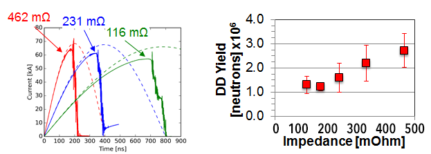
A miniature DPF (Milanese et al. 2003) was selected as a starting point for the modeling, as it had a reported yield of 106 neutrons per pulse, which is approximately 100 times higher than expected yields based on scaling laws. The rise time of the current pulse was varied in the simulation while maintaining the same total energy. This was performed by changing the capacitance of the pulsed power bank driving the DPF. This is a relatively straightforward scan to perform in a simulation since the bank is used as an input to the model and can be predetermined for each run. In the laboratory, however, this is a very difficult parameter to change since the different capacitors are of different sizes, expensive to procure, and labor-intensive to swap out. The simulations predict that the circuit driver with the fastest rise time creates the highest current and neutron yields, and a decision was made to use a low-capacitance, high-voltage driver (Figure 2).
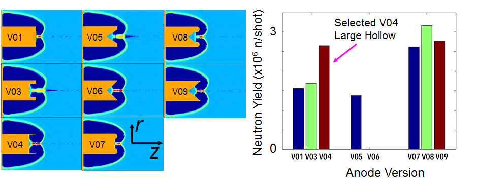
Next, eight different anode shapes that could all be run in parallel in a few days were evaluated in the simulations. By contrast, it takes several days to test a single anode in the laboratory, a process that includes manufacturing the new anode, breaking vacuum, installation, pumpdown, conditioning, and taking measurements. The anode shape scan revealed that anodes with straight hollow holes and conic hollow holes produced the highest yield. It was later understood via modeling that hollow anodes prevent arcing near (but outside) the pinch region, from the plasma sheath to the anode; thus they effectively reduce parasitic losses to the pinch current. Testing a subset of the best anode shape candidates on a different DPF device revealed that the straight hollow anode performed the best and this was eventually implemented in the mini DPF (Figure 3).
Objective 2: Design and construct a DPF for laboratory experiments in the “fast rise time” regime identified in simulations.
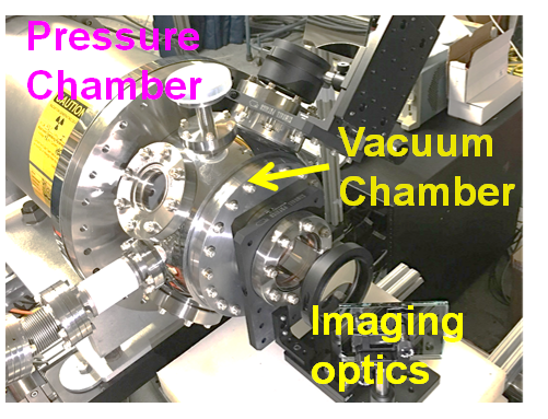
A compact DPF (Figure 4) was designed that mounts the capacitor bank directly to the back of the DPF head. The setup minimizes the driver inductance in order to achieve the fastest possible rise time for the current, which was found to increase the neutron yield of the DPF in the simulations. The DPF head was designed to be swapped out without disassembling the bank to accommodate rapid-prototyping of setups. Innovative concepts were incorporated into the design, such as a radial “insulator” made of semiconducting material that doubles as the guard resistor for compactness.
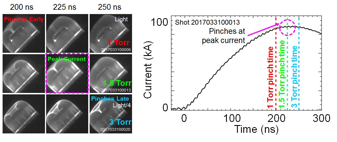
After a series of design reviews, the DPF was constructed and commissioned. The pinch time in the plasma was diagnosed with a series of multiframe fast-framing cameras. By testing several anode lengths, bank currents, and fill pressures, the device could achieve a pinch at the time of maximum current in the circuit. This was aided by using information from the simulations to determine the time to pinch. An example pressure scan is shown in Figure 5. While moving, the sheath aggregates a fraction of the fill gas it passes through based on the ionization rate. A higher fill pressure means the sheath must sweep up more mass and the same electromagnetic force from the driver will result in a slower-moving sheath. By manipulating the fill pressure, the sheath was able to pinch at peak current for this anode–cathode setup.
Objective 3: Update the model using experimental data; then use the new model to inform the next design changes in the laboratory DPF in an iterative feedback loop to maximize neutron yield.
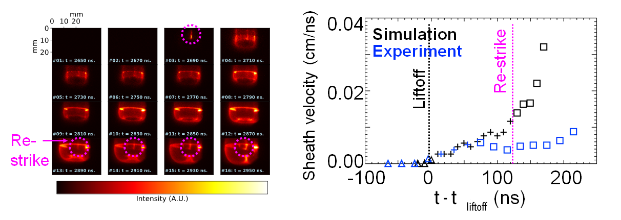
A consequence of low-capacitance, fast-driver DPF setups is the need for higher voltage to keep a large energy density in the capacitors. Our mini DPF was typically charged to 40 kV while the Milanese DPF was charged to 16 kV. Although theoretically a fast driver produces higher yields, fast drivers come with the practical inconvenience of their higher voltage, causing restrikes more easily. This increased the likelihood of restrikes during the pinch, which can divert current away from the pinch area and greatly diminish the beam density, energy, and total DPF yield. Unlike the restrikes close to the pinch that can be prevented with a hollow anode, these restrikes occur further upstream.
After troubleshooting the initial configuration, we determined that the plasma-sheath velocity could only be explained by restrike behavior. Data shown in Figure 6 (right) are the first of their kind, direct comparisons of the sheath position and velocity from the Chicago simulation (black) and the experiment (blue). The sheath velocity, which is directly proportional to the current in the sheath, agrees with the simulations until the restrike is observed. As the current is diverted away from the sheath and through restrike, the measured sheath velocity in the experiment deviates from the simulation. The plasma sheath velocity must be sufficiently high to drive the pinching and produce neutrons. The restrike limits the sheath velocity to 0.08 cm/ns, slower than the 0.2–0.4 cm/ns predicted in the device. No neutron yield was observed on the shot with the restrike.
Not only did the simulation demonstrate the symptom of the problem, it elucidated the cause: the anode–cathode voltage in the simulations temporarily spikes at greater than 250 kV during the pinch, a consequence of the high current for the fast system. Using this information from the simulation, the anode in the laboratory was redesigned with a round undercut facing the cathode to mitigate arcing (see Figure 1). This undercut removes the line-of-sight path from the anode to the cathode, making it harder for free ballistic electrons to arc. The undercut also shields part of the insulator from the ultraviolet light emitted by the plasma, which can seed flashover. The undercut also removes the sharp corner on the anode at the “triple point” where the insulator, vacuum, and anode all come together. Triple-points that occur at a sharp edge can enhance electron emission, which seeds arcs. The redesigned anode led to a faster sheath velocity as expected and improved the reliability of the neutron production.
The visible restrikes that limited the run velocity in the previous anode design were not observed with the rounded anode. The redesign of the anode not only led to faster sheath velocity (approximately 0.02 cm/ns), but the mini DPF now reliably produces neutrons, while the previous anode did not. Figure 7 (left) is similar to Figure 5, with the exception that the evidence of the pinch can clearly be seen in the current traces. Figure 7 (middle) depicts the first neutron yield measurements for two different discharge voltages as a function of fill pressure. In each case there is an optimal fill pressure for producing neutrons that corresponds to the plasma-pinching with a high run-in velocity at peak current. Figure 7 (right) sheds some light on this measurement: In the absence of the restrict restrike, the sheath accelerates to a high velocity during the final stages of the run-in, generating a pinch signature in the current.
The mini DPF successfully demonstrated pinching and neutron production in a compact setup. Simulations of the device were used in an iterative feedback loop to set the driver rise time, anode length and shape, and help identify the restrike issue associated with the compact setup and high voltage.
Impact on Mission
This work supports Lawrence Livermore National Laboratory's mission in global security and nuclear nonproliferation. A compact flash neutron source will provide many opportunities for remote active interrogation systems. The LSP and Chicago codes support many efforts in high-energy-density science at the Laboratory. The simulations conducted during this project were very useful in validating the code used in many efforts at the Laboratory. The project partially funded three postdocs and four staff scientists during their first year at Livermore, providing training and work experience that would enable them to join Livermore's DPF programmatic efforts.
Conclusion
The miniature DPF research project has received follow-on programmatic support to improve the yields and compactness of the device. Compact neutron sources are attractive candidates for many global security applications of interest to the DOE and DOD. The mini DPF continues to benefit the DPF group by providing a platform for code benchmarking and rapid prototyping of new concepts. Knowledge gained from the mini DPF is used to improve the designs of the larger kilojoule DPF, as well as a megajoule DPF under construction.
References
Milanese, M., et al. 2003. “D-D Neutron Yield in the 125 J Dense Plasma Focus Nanofocus.” The European Physics Journal D (27):77. doi: 10.1140/epjd/e2003-00247-9.
Schmidt, A., et al. 2012. “Fully Kinetic Simulations of Dense Plasma Focus Z-Pinch Devices.” Physical Review Letters 109: 205003. doi: 10.1103/PhysRevLett.109.205003.
———. 2014. “Comparisons of Dense Plasma-Focus Kinetic Simulations with Experimental Measurements.” Physical Review E 89, 061101(R). doi: 10.1103/PhysRevE.89.061101. LLNL-JRNL-650219.
Thoma, C., et al. 2017. “Hybrid-PIC Modeling of Laser Plasma Interactions and Hot Electron Generation in Gold Hohlraum Walls.” Physics of Plasmas 24, 062707. doi: 10.1063/1.498531.
Publications and Presentations
Cooper, C. M., et al. 2016. “Construction of a Compact, Low-Inductance, 100 J Dense Plasma Focus for Yield Optimization Studies.” 58th Annual Meeting, American Physical Society Division of Plasma Physics, October 31–November 4, 2016, San Jose, CA. LLNL-ABS-827644.
———. 2016. “Construction of a Compact, Low-Inductance, 100 J Dense Plasma Focus for Yield Optimization Studies.” Conference on Laser Energy Science / Laser and Accelerator Neutron Sources and Applications, May 17–20, 2016, Yokohama, Japan. LLNL-ABS-864464.
Higginson, D., et al. 2016. “AmBe Source Replacement via Dense Plasma Focus (DPF) Z-Pinch.” International Conference on Nuclear Security: Commitments and Actions, December 5–9, 2016, Vienna, Austria. LLNL-POST-711177.
Holod, I., et al. 2017. “Using Solid Targets to Enhance Neutron Yield in a Deuterium Gas-filled Dense Plasma Focus.” Dense Z-Pinches Conference, August 13–17, 2017, Lake Tahoe, CA. LLNL-POST-736596.
Jiang, S., et al. 2016. "Study on the Polarity Riddle of the Dense Plasma Focus." 58th Annual Meeting of the APS Division of Plasma Physics. LLNL-ABS-697681.
Liu, J. X., et al. 2016. "Seeding the m=0 Instability in Dense Plasma Focus Z Pinches." 58th Annual Meeting American Physical Society Division of Plasma Physics, October 31–November 4, 2016, San Jose, CA. LLNL-ABS-697806.
McMahon, M. et al., 2016. "Optimizing Dense Plasma Focus Neutron Yields with Fast Gas Puffs". 58th Annual Meeting American Physical Society Division of Plasma Physics, October 31–November 4, 2016, San Jose, CA. LLNL-ABS-697538.
Povilus, A., et al. 2016. "Preionization Techniques in a kJ-Scale Dense Plasma Focus". 58th Annual Meeting American Physical Society Division of Plasma Physics, October 31–November 4, 2016, San Jose, CA. LLNL-ABS-697764.
Schmidt, A., et al. 2015. “Kinetic Simulations of Dense Plasma Focus Breakdown.” 57th Annual Meeting of the American Physical Society Division of Plasma Physics, November 16–20, 2015, Savannah, GA. LLNL-ABS-675188.
———. 2016. "Optimization of Intense DPF Z-Pinch Neutron Source via Experiments and Kinetic Modeling". Hardened Electronics And Radiation Technology TIM. LLNL-ABS-677487.
Sears, J., et al. 2016. "The Effect of Driver Rise-Time on Pinch Current and its Effect on Plasma Focus Performance and Neutron Yield". 58th Annual Meeting of the American Physical Society Division of Plasma Physics. LLNL-ABS-697680.
Sears, J., et al., 2015. “The Role of the Driver Circuit in Chaotic Processes and the Neutron Yield of the Plasma Focus.” 57th Annual Meeting of the American Physical Society Division of Plasma Physics, November 16–20, 2015, Savannah, GA. LLNL-ABS-670450.


