Emily Link (15-FS-009)
Abstract
We evaluated the limitations of conductive cooling for high-repetition-rate, high-energy, short-pulse titanium–sapphire laser systems for face conductive and edge conductive cooling. A thermal model was generated to determine fracture tolerances under average power operation and discovered that parameters resulting from the thermal models were limited further by considering the effects of amplified spontaneous emission and nonlinear phase accumulation. We determined that edge cooling of titanium–sapphire rods with low doping concentration has superior average power performance compared to face conduction, which is limited in its range of efficacy. However, face conduction may still be advantageous because of the decreased thermal lens. Edge cooling should be feasible up to an average power of 8 kW.
Background and Research Objectives
High-energy, high-peak-power laser systems are of great interest to the high-energy-density physics and basic-energy-science communities and important to several DOE missions. These short-pulse lasers are used for generating and probing warm and hot dense matter through the generation of a secondary source such as x rays, electron beams, and ion beams. Proof-of-principle experiments have been demonstrated on single-shot laser systems ranging from high-energy-density plasma generation and probing, shock drivers and probing for equation-of-state studies, laser particle acceleration for advanced imaging and medical applications, and coherent and incoherent x-ray generation. However, sufficient data acquisition to ensure good data quality has been hampered by the very limited shot rate. Furthermore, laser secondary-source applications such as advanced imaging for defense or medical applications will typically require kilowatt to tens of kilowatt average power, and industrial applications such as high-speed laser cutting and precision micro-machining of special materials require very short pulses and high average power. It is therefore necessary to increase the average power of high-energy, short-pulse laser systems to the kilowatt level and beyond to access these applications.1 The increased availability and affordability of laser diodes makes the development of such high-average-power lasers possible, but the next step toward realizing high repetition rates lies in understanding the requirements for heat removal from the laser gain medium. Our objective in this study was to model heat extraction from the titanium–sapphire laser medium (sapphire crystal doped with titanium ions) to determine if conductive cooling, in which the heat is transferred from the optical gain medium (laser crystal) to the surrounding medium, is feasible for multi-Joule short-pulse laser systems.
For high-peak-power, short-pulse lasers, titanium–sapphire is a popular gain material because of its high optical quality, large-gain bandwidth, and available large crystal size (up to 20 cm diameter). Titanium–sapphire is also applicable for high-average-power laser systems because of its high thermal conductivity, and has been deployed in commercial laser systems with multi-watt average power. The current state of the art in small-aperture, high shot-rate titanium–sapphire lasers requires edge conductive cooling at cryogenic temperatures to decrease thermal lensing effects and wave-front distortions. 2,3 Cryogenic cooling is difficult and costly for large-aperture, high-pulse energy systems. Gas-based face cooling has been demonstrated for nanosecond repetition-rated laser systems such as the Mercury diode-pumped solid-state laser at LLNL, but such cooling is also complex and costly.4,5 Extensive literature is available for cooling yttrium–aluminium–garnet and other yttrium-containing gain media.6–8 The material properties of titanium–sapphire are well known, but face-cooled conductive cooling has not been explored. For large-aperture, high-energy laser systems (>10 J) based on titanium–sapphire, average power has been demonstrated with 23 W at the Lawrence Berkeley National Laboratory Laser Accelerator petawatt laser facility (22.7 J before compression at 1 Hz) in Berkeley, California, using edge cooling.9,10 Average power has also been demonstrated at greater than 60 W at Colorado State University, Fort Collins, Colorado (32 J before compression at multiple hertz).11 At the Laboratory of Applied Optics, Palaiseau, France, medium-aperture, medium-energy laser systems (3–10 J) based on titanium–sapphire have demonstrated 36 W (3.6 J before compression at 10 Hz) using cryogenic edge cooling.12 Face cooling using flowing gas, proposed by LLNL for the High-Repetition-Rate Advanced Petawatt Laser System to be installed in the European Union’s Extreme Light Infrastructure Beamlines facility under construction in the Czech Republic, has predicted an average power of 600 W (60 J before compression, at 10 Hz).
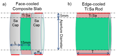
Efforts to scale short-pulse lasers to higher repetition rates with average power in the kilowatt range and beyond will require further study of the heat removal mechanisms and the physics in the gain medium. To that end, we investigated the fundamental limitations of two competing cooling technologies, shown in Figure 1. Figure 1(a) shows a proposed geometry for face conductive cooling of a composite slab comprising a 15-mm titanium–sapphire slab between two undoped sapphire caps, of length L, for face cooling. The thermal interface is applied around the edge of the undoped sapphire in a cylinder of width w, as indicated in red. Figure 1(b) shows the geometry for edge cooling along a titanium–sapphire rod of length T. The thermal interface is applied along the entire length of the rod for maximum surface area, as indicated in red. Both geometries receive uniform heat deposition in only the titanium–sapphire material in a simulated beam aperture that is 10-mm smaller than the total diameter of the material.
Scientific Approach and Accomplishments
Our approach was to build a thermal model and evaluate the maximum average power under steady-state conditions before material fracture as a function of aperture size and length. The temperature gradients simulated at the fracture limit were used to check the severity of the thermal lens. The thermally limited set of operation parameters was further restricted based on estimates for amplified spontaneous emission and accumulated nonlinear phase for each amplifier. Finally the limits of the two methods were compared to determine relative efficacy.
Using ANSYS Workbench, a commercial software system that includes modeling, meshing, fluid, multiphysics, structural, dynamics, electro-magnetics, and turbo-system components, we generated a thermal model with a list of geometry and boundary condition input parameters. The model was limited to conduction, constant temperature boundary conditions at the cooled surfaces, and volumetric energy input within the titanium–sapphire aperture. In this simplification, the assumption is made that the chosen cooling technique (e.g., gas or liquid convection, solid conduction, radiation, or some combination) is sufficient to keep the boundary at the temperature specified. The model with complete parameters was then programmed to obtain thermal solutions for thousands of combinations of geometric and thermal inputs. Post-processing of these thermal solutions indicates that the heat-transfer coefficients at the cooling boundaries are within typical ranges for conventional cooling methods. Liquid-forced convection at less than 1 W/cm²K was commonly sufficient, and rarely would a result require the higher coefficients of more exotic transfer fluids.13 Transitions from titanium–sapphire to sapphire are assumed to be ideally bonded, without any additional thermal resistance across the boundaries. Each thermal solution was then passed to the static structural portion of ANSYS Workbench to obtain stress solutions for each geometric and thermal input combination. These solutions were passed to routines in the MATLAB technical computing language for interpolation to determine the thermal power input values that would result in stress fracture within the sapphire or titanium–sapphire. We assumed a flaw size of 50 µm in the materials, approximately a factor of two above typical flaw sizes for titanium–sapphire. Finally, these stress fracture-limit combinations were run back through the thermal and structural models to confirm proper interpolation and to obtain thermal profiles at the stress fracture limits to use for thermal lens calculations.
To understand the effect of the thermal gradient on the amplifier, we used the temperature profile in the slab to estimate the phase change from thermally induced changes in the index of refraction. Comparing this phase change to that of a thin lens, we can estimate the effective focal length of the thermal lens.
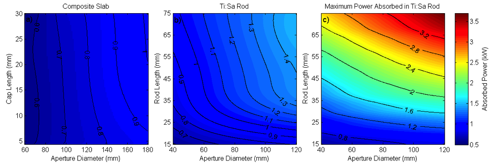
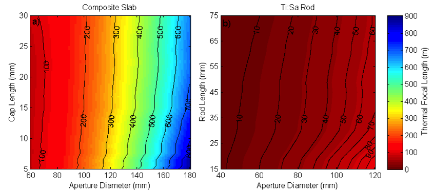
We determined that the maximum thermal power is achieved for a single rod with edge cooling. The absorbed power at the fracture limit is plotted in Figure 2. The amount of heat removed from the amplifier slab is proportional to the surface area available for heat removal, so it is difficult to directly compare long rods to the thin composite-slab geometry with a smaller cooled surface area. Additionally, geometry variations between the two scenarios caused thermal gradients to be quite different. When the thermal interface was limited to the ends of the slab assembly, the thermal gradient was forced to be more longitudinal than transverse, significantly impacting the thermal lens. As the width of the thermal interface (indicated by w in Figure 1) decreases, the thermal gradient becomes increasingly longitudinal, but at the cost of decreased cooling surface area. To directly compare the composite-slab cooling to that of the long rod, we limited the thermal interface width for both geometries to 3.75 mm at the ends of the slab assembly. The maximum thermal power for this short cooling region is shown in Figure 2(a) for composite slabs and in Figure 2(b) for edge-cooled rods. The maximum power for a rod with the entire edge surface cooled is shown in Figure 2(c). The thermal lens estimates corresponding to the shortened cooling region are included in Figure 3.
In titanium–sapphire, a single, long rod produces superior average power performance to composite slabs because the fracture toughness for titanium–sapphire is higher than that for undoped sapphire, leading to earlier fracture. However, our thermal lens analysis indicated an improvement in thermal lens by a factor of three to five with face cooling.
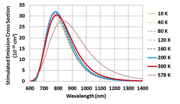
The last issue concerning thermal modeling is optical performance. The high-temperature performance of titanium–sapphire has not been studied because of the decreasing fluorescence lifetime of titanium–sapphire at high temperatures.14 It is possible to gain a hint of the high-temperature behavior of the material by studying published fluorescence spectra.15,16 By fitting the spectra to a Poisson distribution, we can reconstruct the stimulated emission cross section as a function of temperature.17 The calculated cross section is plotted in Figure 4. As temperature is increased, the cross section broadens and undergoes a red shift. The fluorescence lifetime may limit the maximum operating temperature to a value under 578 K for some applications. The broadening of the cross section indicates that the gain bandwidth can be increased by increasing slab temperature. This preliminary model is promising, but in need of experimental validation.
The amplified spontaneous emission and accumulated nonlinear phase in the amplifier system limit the operating range of the slabs, but require some assumptions about the amplifier architecture. We assumed a 4-pass amplifier with a single pass gain of 3, efficient extraction with an output fluence of 2.2 J/cm2, and a stretched pulse duration of 1 ns. We adjusted the doping concentration as the total titanium–sapphire length is changed to maintain equal gain. A split-step Franz–Nodvik model is used to calculate the energy and B-integral accrued for this four-pass amplifier based on the geometries studied. (The B-integral is a measure of the nonlinear phase shift.) In the composite slabs, the 15-mm titanium–sapphire is too thin to maintain a single pass gain of 3 with a doping concentration that can be manufactured. To ensure a reasonable doping concentration, it is necessary to use at least two composite slab assemblies per amplifier. Using multiple slabs increases the material path length, increasing the accumulated nonlinear phase, but also increases the average power because the heat load limit is applied to each slab. The total accumulated nonlinear phase degrades pulse performance because it cannot be compensated in pulse compression. We limited the accumulated nonlinear phase from the final amplifier to be under 0.5 rad based on experience from other systems. As the number of slabs increases, the end caps must become shorter, so we limited the number of slabs to four to maintain cooling efficiency. Edge-cooled rods can support a rod length up to about 100 mm before the accumulated nonlinear phase becomes too large.
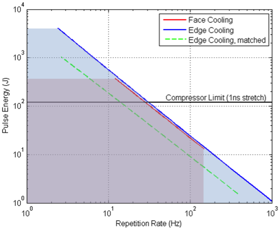
The maximum aperture size that can be used in the amplifier is limited by amplified spontaneous emission. Amplified spontaneous emission becomes too large when the transverse gain is greater than about 8. Because the transverse gain is proportional to both the doping concentration and the aperture size, slabs with lower doping concentration will be able to reach larger aperture sizes. The highest pulse energies are reached by using four composite slab assemblies or the longest edge-cooled rod feasible. The maximum beam energy is also limited by the pulse-compression optics. The damage threshold of a diffraction grating requires fluences no more than 0.1 J/cm2. For the largest gratings available, with about a 1-m diagonal, the energy is limited to a few hundred joules. Thus, advances in both amplified spontaneous emission mitigation and diffraction-grating damage threshold will be necessary for larger pulse energies in titanium–sapphire amplifiers.
Figure 5 shows the limitations of conductive cooling in titanium–sapphire achieved by applying the constraints on length and aperture size, resulting from the accumulated nonlinear phase and amplified spontaneous emission, to the thermal models. Because of the increased surface area for the cooling interface and the lower doping, long edge-cooled rods have superior performance in pulse energy compared to face-cooled composite slabs. In the range where face and edge conduction behaved similarly, the smaller thermal lens of face conduction may be advantageous, and complete wave-front analysis may be required to determine the best method.
Impact on Mission
Advances in heat removal from broadband amplifiers are critical to scaling high-energy and short-pulse, diode-pumped solid-state laser technology to high average powers. Our modeling effort in this area, therefore, is directly relevant to the Laboratory’s core competency in laser and optical materials science and technology.
Conclusion
Thermal models, gain calculations, and accumulated nonlinear phase estimates were used to determine the limits of face conduction and edge conduction cooling in titanium–sapphire amplifiers. Our models indicate that multiple-joule titanium–sapphire lasers should be able to produce average powers from 1 to 8 kW, with pulse energies up to a maximum of 4 kJ (at 2 Hz) via edge conductive cooling. Face conductive cooling has a limited operation range, but may be advantageous in reducing thermal lens effects. Where higher temperatures (>100°C) are considered, the broadening and reduction in stimulated cross section must be evaluated. In the region where face and edge conduction behave similarly, full wave-front models will be required to determine which method will be most effective. Our models indicate that conductively cooled titanium–sapphire should achieve 8 kW operation for edge cooling and 2.5 kW for face cooling with reduced thermal lens.
References
- Department of Energy, Summary Report of the Workshop on Laser Technology for Accelerators, January 23–25, 2013. http://science.energy.gov/~/media/hep/pdf/accelerator-rd-stewardship/Lasers_for_Accelerators_Report_Final.pdf
- Zavelani-Rossi, M., et al., “Control of thermal effects for high-intensity Ti:sapphire laser chains.” Appl. Phys. B 70, S193 (2000).
- Schulz, P. A., and S. R. Henion, “Liquid-nitrogen-cooled Ti:Al2O3 laser.” IEEE J. Quant. Electr. 27(4), 1039 (1991).
- Bayramian, A., et al. “The Mercury project: A high average power, gas-cooled laser for inertial fusion energy development.” Fusion Sci. Tech. 52, 383 (2007).
- Marshall, C. D., et al., “Diode-pumped gas-cooled-slab laser performance.” OSA TOPS on Adv. Solid-State Lasers 1, 208 (1996).
- Eggleston, J. M., et al., “The slab geometry laser—Part I: Theory.” IEEE J. Quant. Electron. QE-20, 289 (1984).
- Weber, R., et al., “Cooling schemes for longitudinally diode laser-pumped Nd:YAG rods.” IEEE J. Quant. Electron. 34(6), 1046 (1998).
- Koechner, W., “Transient thermal profile in optically pumped laser rods.” J. Appl. Phys. 44, 3162 (1973). http://dx.doi.org/10.1063/1.1662725
- Laux, S., et al., “Suppression of parasitic lasing in high energy, high repetition rate Ti:sapphire laser amplifiers.” Optic. Lett. 37, 1913 (2012).
- Leemans, W. P., et al., "Multi-GeV electron beams from capillary-discharge-guided subpetawatt laser pulses in the self-trapping regime." Phys. Rev. Lett. 113, 245002 (2014).
- Rockwood, A., et al. “Petawatt class laser with high repetition rate for excitation of x-ray lasers.” Annual Mtg. APS Four Corners Section, October 16–17, 2015, vol. 60, Abstract: B1.00002.
- Planchon, T. A., et al., “Adaptive wavefront correction on a 100-TW/10-Hz chirped pulse amplification laser and effect of residual wavefront on beam propagation.” Optic. Comm. 252, 222 (2005).
- Incropera, F. P., and D. P. DeWitt, Introduction to heat transfer, 4th ed. John Wiley and Sons, Inc., New York, NY (2002).
- Moulton, P. F., “Spectroscopic and laser characteristics of Ti:Al2O3.” J. Opt. Soc. Am. B 3, 125 (1986).
- Delaigue, M., et al., Spectroscopic and lasing properties of Ti:sapphire at low temperatures. CLEO Europe 2007, Munich, Germany, June 17–22, 2007.
- Byvik, C. E., et al.,“Analysis of vibronic transitions in titanium-doped sapphire using the temperature of the fluorescence spectra.” IEEE J. Quant. Electron. QE-21, 1619 (1985).
- Eggleston, J. M., et al., “Characteristics and kinetics of laser-pumped Ti:sapphire oscillators.” IEEE J. Quant. Electron. 24, 1009 (1988).


