Robert Panas (13-ERD-009)
Abstract
In this project, we introduced a new flexure topology, generated a new method for modeling and optimization of actuator performance, and developed a hybrid conventional and additive manufacturing technique for the fabrication of a high fill-factor (99%) micro-mirror array (10,000 1-mm2 mirrors). The micro-mirrors are designed to be driven with three degrees of freedom—tip, tilt, and piston—over large ranges (±10° rotation and greater than ±30-µm translation) at high speeds (~40-kHz small stepping rate), all with continuous closed-loop control. The capabilities of this new mirror array will extend the performance of a variety of high-impact technologies for fusion energy research, additive material manufacturing, and diagnostics. The initial fabrication effort focused on generating an independently controllable seven-mirror prototype, and the designs were vetted against finite-element analysis and a full range of previous capabilities as described in the literature. We successfully produced the critical elements of the system: mirrors, hexapods, and actuation paddles. in addition, we developed a new transfer process to handle the hybrid component assembly and demonstrated this process on elements of increasing complexity.
Background and Research Objectives
This research project focused on creating a new micro-mirror array to simultaneously direct multiple high-powered beams of light in various directions at high speeds. This device, known as a light-field directing array, is an independently controlled and scalable mirror array designed to achieve independent continuous control with speeds, ranges, array sizes, and light fill-factors otherwise unachievable. The array would enable advanced applications for rapid steering of multiple high-powered laser beams for detonating targets for inertial fusion, true auto-stereoscopic images, multiple-material nanometer-scale fabrication using laser beams focused by a high-quality microscope objective (optical tweezers), and ultrarapid multiple-focal-point optical remote sensing or confocal microscopy.
Tip, tilt, and piston micro-mirror arrays have been a topic of significant interest since the 1980s.1 Applications, which drove the development of such arrays, included optical cross-connects, image projection, object tracking, adaptive optics for aberration correction, and laser scanning and steering.1–9 Micro-mirrors offer a faster and potentially more reliable alternative to macroscopic steering optics (galvanometers). Discrete arrays with piston capability also offer the potential to integrate phase control into the beam steering.
Robotics (imaging and sensors) and laser development pushed the need for beam-steering mechanisms with increased power handling as well as speed, range, and precision. No current micro-mirror system has attempted to simultaneously meet all of these requirements. The LLNL light-field directing array was designed specifically to push the performance bounds of micro-mirrors in all these parameters: size, speed, range, and precision. The light-field directing array chip was designed to perform ±10° sweeps, with a bandwidth of 40+ kHz, and tip–tilt–piston closed-loop motion control over large (≈10 x 10 cm) arrays.
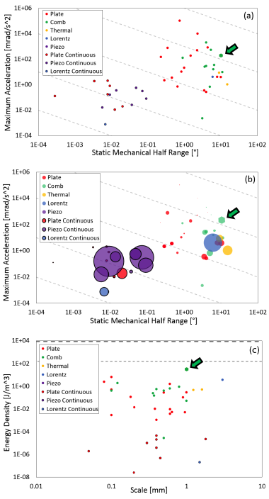
The green hexagons shown in Figure 1(a–c) represent the performance capabilities of a "comb discrete" micro-mirror array design used for this project. (Comb drives are capacitive actuators, typically operating at the micrometer or nanometer scale, that utilize electrostatic forces that act between two electrically conductive combs.) All surveyed tip–tilt micro-mirror arrays are shown in Figure 1(a). These points are then scaled by mirror pitch and displayed in Figure 1(b). Mirror pitch is a critical parameter for controllability: if the pitch is too small, the trace density will be too high for individual control. By comparison, the micro-mirror arrays with similar or better dynamic capabilities have much smaller single-mirror size. Figure 1(c) shows the energy density of various designs, providing a metric of comparison for the actuator design quality.
Figure 1. Maximum acceleration versus range for our micro-mirror surveyed arrays. (a) All surveyed tip–tilt micro-mirror arrays. (b) Points in graph (a) above, scaled by mirror pitch. (c) Energy density of various designs, providing a metric of comparison for the actuator design quality.
Our research objectives were to (1) fully explore and extend beyond the current state of the art for the micro-mirror field, (2) design mirror topology by developing the correct fundamental layout of the elements in the light-field directing array, (3) design actuators that boosted actuation capability, (4) develop a fabrication method that could produce both the actuators and critical flexures in the system, (5) demonstrate the fabrication method on a single cell, and (6) demonstrate the fabrication method on a seven-mirror array.
Scientific Approach and Accomplishments
Our first objective focused on establishing the state of the art in micro-mirror technology to gauge commercial capability and leverage recent technology advances to drive our design. We developed metrics for comparing mirror technologies including range-versus-resolution charts as well as actuation energy density (Figure 1). Our efforts resulted in the largest known analysis of current micro-mirror technology and provided critical insights into the necessary design and actuation physics required to reach our goal of high speed and large range. Additionally, our analysis has been used for other projects to determine what systems to employ and to explore technology limitations.
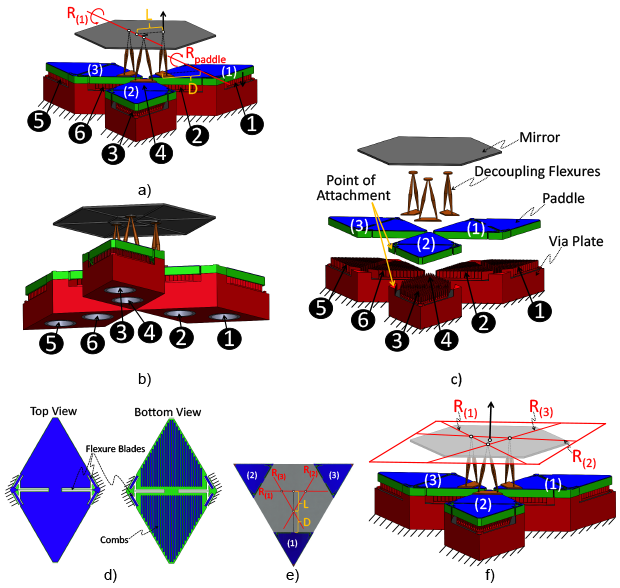
After our initial analysis was complete, we moved forward with our second objective to design the mirror topology, focusing on developing the correct fundamental layout of the elements in the light-field directing array. This effort resulted in a new topology with exact constraint (not achieved in most other mirror designs) and decoupled actuators for easy control. The design, which out-performed existing systems by over an order of magnitude, utilized flexural design theory as well as constraint-based actuator optimization. Flexural design theory was used to synthesize the array’s flexures such that they (1) only permit the three desired degrees of freedom, (2) are symmetric and exactly constrained, (3) decouple each mirror’s actuators, (4) do not permit any under-constrained bodies, and (5) behave as transmission elements.
A single hexagonal mirror within the repeating array is shown with different views in Figures 2(a) and 2(b), and an exploded view of the system is shown in Figure 2(c). The mirror is constrained by three identical axisymmetric serial-flexure limbs (decoupling flexures) in Figure 2(c). The other parallel module consists of six blade flexures shown in Figure 2(d), which join the corresponding paddle to the fixed "via" charged-comb actuation plate.
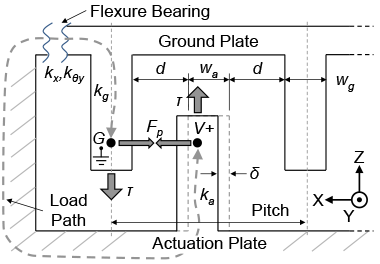
For the third objective, we redesigned the comb drive actuator to boost performance. Comb drives have been the focus of extensive optimal design efforts. In particular, instability from the actuator pulling inward has been extensively studied.10–14 A range of additional effects have also been considered including bearing stiffness and varying comb cross-section.11,12 These efforts typically focus on deducing a critical stiffness for design and take the comb geometry as given. Our work operated in the opposite direction. The optimizer draws upon given flexure bearings, which have been designed via flexural design theory to find the comb geometry that maximizes actuation within the given design topology and geometric constraints. We developed a new method to analyze the actuator pull-in that extends beyond previous work so as to incorporate both fabrication errors and the stiffness of the full-load path loop, shown in Figure 3, into closed-form analytical expressions for pull-in displacement. This expression is integrated into a new approach to comb-drive design which uses constraint-based optimization. Using this approach enabled us to design actuators with tenfold greater energy density than previous comb designs.
Figure 3. Schematic of the comb overlap, showing main geometry, stiffnesses, alignment error δ, and the full-load path.
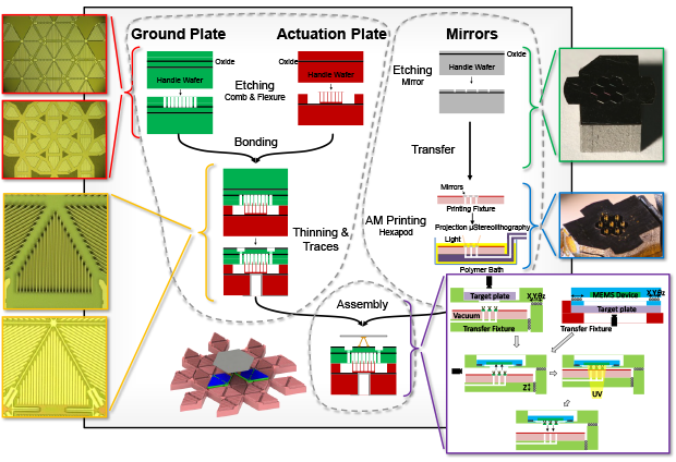
The fourth objective of our work focused on developing the fabrication process required to produce the complex flexure and actuator topology. The mirrors are assembled from a micro-fabricated actuation plate and micro-stereolithographically generated hexapod flexures, which are printed onto the underside of micro-fabricated silicon hexagonal mirrors. The process limitations were characterized for both the micro-fabrication and the additive manufacturing processes. An improved parallel assembly process was developed for handling all seven mirrors to generate the seven-element array. This fabrication process is shown schematically in Figure 4. The micro-fabrication of the actuation plate is shown in the top left corner, highlighting the creation of the combs and guide flexures for the actuator paddles. The micro-fabrication of the mirrors (shown in top right of the image), leads to the additive manufacturing of the flexural hexapod behind each mirror. These elements are then combined in a parallel assembly process, shown in the bottom middle. Each part of this process has been tested and demonstrated.
Impact on Mission
A mirror-array design that can be used for rapid high-power laser target tracking supports the LLNL mission focus area in Inertial Confinement Fusion energy. Furthermore, this mirror array could be used to guide a massive array of optical-tweezer laser beams in an effort to move and sinter in place millions of nanometer-scale particles simultaneously, which would be a fundamental advance in meta-material additive manufacturing, in support of the LLNL core competency in advanced materials and manufacturing.
Conclusion
The light-field directing array can be viewed as an enabling technology for high-performance optics systems. It combines the capabilities of large aperture (10- x 10-cm) mirrors with adaptive-optics phase modulation at high bandwidths on a single chip. The combined capabilities enable the generation of synthetic optical elements in sub-millisecond time scales, including pseudo-lenses, mirrors, phase plates, beam splitters, and combiners. This provides the potential to replace multiple optical components with a small chip running at high bandwidths and low power draw.
We designed a high fill-factor (99%) micro-mirror array (10,000 1-mm2 mirrors) and developed a new fabrication method to create it. The micro-mirrors are designed to be driven with three degrees of freedom (tip, tilt, and piston) over large ranges (±10° rotation and greater than ±30-µm translation) at high speeds (~40-kHz small stepping rate), all with continuous closed-loop control. This is an order-of-magnitude boost in range speed and a step forward in precision control of similar arrays and degree-of-freedom capabilities.
We have been pursuing two major directions for further development. The first is precision optical tracking in active environments, which is being considered for both missile tracking and laser communications. The closed-loop control of the array provides a means to reject disturbances between platforms, including atmospheric turbulence, machine vibration, and maneuvering. Plans are underway to develop this tracking system with industry sponsors such as Raytheon in Sunnyvale, California, and Lockheed Martin in San Jose, California. The second area for future development is high-energy beam steering. A mature, large-scale light-field directing array is desired by Livermore's National Ignition Facility for high-energy beam control. We are using the understanding gained in this research project to produce a working seven-mirror array demonstrator. Discussions are also underway with external sponsors with the intent of setting up cooperative research and development agreements to support the next phase of the mirror development at large-array scales.
References
- Milanovic, V., G. A. Matus, and D. T. McCormick, “Gimbal-less monolithic silicon actuators for tip–tilt–piston micromirror applications.” IEEE J. Sel. Top Quant. Electron. 10(3), 462 (2004).
- Chu, P. B., et. al., “Design and nonlinear servo control of MEMS mirrors and their performance in a large port-count optical switch.” IEEE ASME J. Microelectromech. Syst. 14(2), 261 (2005).
- Tsai, J., et al., “Two-axis MEMS scanners with radial vertical combdrive actuators—Design, theoretical analysis, and fabrication.” J. Optic. Pure Appl. Optic. 10(4), 044006 (2008).
- Wu, L., et al., “A large-aperture, piston-tip-tilt micromirror for optical phase array applications.” Proc. IEEE 21st Intl. Conf. Micro Electro Mechanical Systems, MEMS 2008, p. 754. Curran Associates, Inc., Red Hook, NY (2008).
- Cowan, W. D., et al., “Surface micromachined segmented mirrors for adaptive optics.” IEEE J. Sel. Top Quant. Electron. 5(1), 90 (1999).
- Dagel, D. J., et. al., “Large-stroke MEMS deformable mirrors for adaptive optics.” IEEE ASME J. Microelectromech. Syst. 15(3), 572 (2006).
- Jain, A., and H. Xie, “A single-crystal silicon micromirror for large bi-directional 2D scanning applications,” Sensor. Actuator. Phys. 130–131, 454 (2006).
- Jia, K., S. Pal, and H. Xie, “An electrothermal tip–tilt–piston micromirror based on folded dual S-shaped bimorphs.” IEEE ASME J. Microelectromech. Syst. 18(5), 1004 (2009).
- Pardo, F., et. al., “Flexible fabrication of large pixel count piston–tip–tilt mirror arrays for fast spatial light modulators.” Microelectron. Eng. 84(5–8), 1157 (2007).
- Legtenberg, R., A. W. Groeneveld, and M. Elwenspoek, “Comb-drive actuators for large displacements.” J. Micromech. Microeng. 320, 320 (1996).
- Trutna, T. T, and S. Awtar, “An enhanced stability model for electrostatic comb-drive actuator design.” ASME 2010 Intl. Design Engineering Technical Conf. and Computers and Information in Engineering Conf. (IDETC/CIE2010), vol. 2. ASME, New York, NY (2010).
- Engelen, J. B. C., L. Abelmann, and M. C. Elwenspoek, “Optimized comb-drive finger shape for shock-resistant actuation.” J. Micromech. Microeng. 20, 105003 (2010).
- Grade, J. D., H. Jerman, and T. W. Kenny, “Design of large deflection electrostatic actuators.” J. Microelectromech. Syst. 12, 335 (2003).
- Olfatnia, M., et al., “Large range dual-axis micro-stage driven by electrostatic comb-drive actuators.” J. Micromech. Microeng. 23, 105008 (2013).
Publications and Presentations
- Hopkins, J. B., R. M. Panas, and Y. Song, Categorization and review of existing micro-mirror array technologies. 30th Ann. Mtg. American Society for Precision Engineering, Austin, TX, Nov. 1–6, 2015. LLNL-CONF-676358.
- Hopkins, J. B., and R. M. Panas, Flexure design for a high-speed large-range tip-tilt-piston micro-mirror array. 29th Ann. Mtg. American Society for Precision Engineering, Boston, MA, Nov. 9–14, 2014. LLNL-ABS-658144.
- Panas, R. M., and J. B. Hopkins, Actuator design for a high-speed large-range tip-tilt-piston micro-mirror array. 29th Ann. Mtg. American Society for Precision Engineering, Boston, MA, Nov. 9–14, 2014. LLNL-ABS-657938.
- Panas, R. M., and J. B. Hopkins, Lightfield directing array. (2014). LLNL-POST-655689.
- Panas, R. M., et al., Hybrid additive and micro-fabrication of an micromirror array. 30th Ann. Mtg. American Society for Precision Engineering, Austin, TX, Nov. 1–6, 2015. LLNL-CONF-676306.


