Lisa Poyneer (14-ERD-056)
Abstract
In the last two decades, adaptive optics systems in astronomy have advanced from concept demonstrations to scientific mainstays, opening entirely new scientific frontiers, such as the first ground-based images and spectra of faint exoplanets orbiting other stars. Adaptive optics also have the potential to correct internal distortions and provide new, adaptive modes of operation for scientific use when applied to bright, nearly coherent x-ray light sources. We have advanced the technique of adaptive x-ray optics from single components (e.g., a deformable mirror and a metrology method) to an integrated, validated understanding of complete system performance. To do so, we custom designed and built an x-ray experiment and deployed it with our best-in-class, 45-cm long, x-ray deformable mirror at the Advanced Light Source at Lawrence Berkeley National Laboratory. We demonstrated a unique capability to custom-shape the x-ray beam profile to arbitrary shapes. We used a grating interferometer to measure the wave-front distortion and “closed the loop” of imaging and feedback in real time, commanding the x-ray deformable mirror to within 3-nm root mean square of the desired surface figure. For this process, detailed, physics-based simulations were used to validate performance. The next step in adaptive x-ray optics advancement will be designing a specific scientific experiment at a light source, such as producing a customized beam profile for a material science experiment.
Background and Research Objectives
All optical systems have distortions, whether they are internal figure errors on optics, or external sources such as atmospheric turbulence. Adaptive optics is a technique to correct these distortions in real time, and works by first measuring error in the incoming light. Electronic signals are then sent to a deformable mirror, which rapidly changes its surface figure to correct the wave front. In the last two decades, adaptive optics systems in astronomy have advanced from concept demonstrations to scientific mainstays, opening entirely new scientific frontiers such as the first ground-based direct images and spectra of faint exoplanets orbiting other stars. Adaptive optics has the potential, when applied to bright, nearly coherent x-ray light sources, to correct internal distortions1 and provide new, adaptive modes of operation such as customized beam-shaping for scientific use.
Our proposed goal was to build and evaluate the performance of the world's first real-time adaptive x-ray optics system, using Livermore's best-in-class, 45-actuator x-ray deformable mirror with a wave-front sensor in experiments conducted at Lawrence Berkeley's Advanced Light Source. We have successfully closed the loop and controlled the x-ray deformable mirror to a repeatable figure with 3-nm root-mean-square height residual error, operating at 0.25 Hz. With this project, we have achieved the following milestones:
- Flattening of the x-ray deformable mirror to just 0.7-nm root-mean-square height figure error with visible-light metrology, which was either the longest or flattest x-ray deformable mirror yet built by a factor of three
- Fielding and successful vacuum (2−6 Torr) operation with x rays of the x-ray deformable mirror, and low-precision metrology
- Development of robust, physically accurate simulation codes validated against x-ray experimental results, which correctly capturing the important effects of Fresnel propagation and the grazing-incidence use of the x-ray deformable mirror
- Demonstration of accurate absolute beam-shaping of the near field, producing customized intensity profiles, and use of nonlinear optimization to produce arbitrary profiles
- Fielding of an x-ray grating interferometer, and demonstration of the measurement of a 2.5-nm root-mean-square height figure change on the x-ray deformable mirror at a signal-to-noise ratio of eight, as designed
- Use of the grating interferometer to drive the x-ray deformable mirror to a known shape in a closed loop, with the best flat shape reached with 3-nm root-mean-square height residual error at a control rate of 0.25 Hz
Scientific Approach and Accomplishments
Our overall technical approach was to develop an integrated and experimentally validated understanding of adaptive x-ray optics system performance. We designed the components to work together (integrated) for a specific purpose—that is, the grating interferometer was designed to measure the necessary spatial frequencies of the x-ray deformable mirror's figure in order to flatten it. We developed detailed, physics-based models to design the experiment, and these simulations were then validated through x-ray experiments. In addition, the specific aspects of the experiment design were verified—for example, checking whether the noise level and spatial frequency range of the metrology as implemented matched the design.
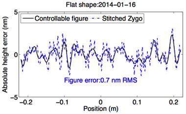
In the first phase of the project, the x-ray deformable mirror was fully characterized with calibrated, visible-light metrology. The mirror actuator responses and linear superposition matched that predicted in its design by finite-element analysis. Using these models and precise fourth-order calibrations of the voltage response, the x-ray deformable mirror was repeatedly flattened to better than 1-nm root-mean-square height figure error,2 as shown in Figure 1.
Figure 1. Precise visible-light metrology and finite-element models of the x-ray deformable mirror response were used to generate voltages that flattened its surface figure across the 45-cm length to better than 1-nm root-mean-square height.
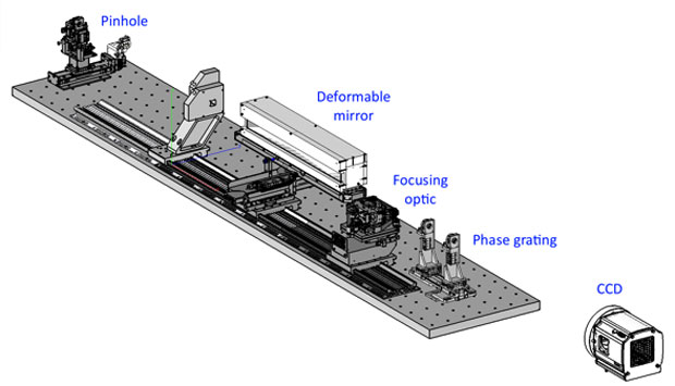
In the second phase of the project, the x-ray experiment to be used at the Advanced Light Source was designed and commissioned, as shown in Figure 2. The gold pinhole filtered the incoming 3-keV monochromatic x-ray beam, producing a clean wave front for experiments. The x-ray deformable mirror, through adjustment of its surface height, modulates the beam. The beam can then be imaged directly onto the charge-coupled device, as is used in the beam-shaping results below. The experiment also had a Kirkpatrick–Baez optic that produces first a focus, then a diverging beam at the detector. This second configuration is similar to most x-ray end stations, which use a focused beam. Furthermore, the focusing optic is necessary to implement high-precision metrology for this experiment.
The experimental setup was designed to provide flexibility for alignment (e.g., adjustable graze angles) and to enable the entire 45-cm length of the x-ray deformable mirror to be utilized. This first in-vacuum use of this x-ray deformable mirror with x rays has led to several lessons learned. While the x-ray deformable mirror functions well at 2−6 Torr, its internal strain gauges cannot be powered continuously, because this results in significant heat build-up in the mirror and shape distortions. Future versions will require active cooling. Our experiment placed stringent requirements on the quality of the incoming beam from the synchrotron. Unanticipated problems with this necessitated an upgrade of the beam-line monochromator and design and installation of an additional harmonic suppression system, with associated schedule delays.
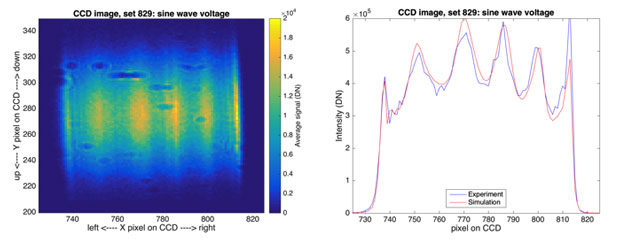
The near-field beam-shaping scenario provided a relatively simple first validation test for the adaptive x-ray optics system. In this case, no focusing optic was used. There are only three components in the system: the pinhole, the x-ray deformable mirror, and the detector. Though a deformable mirror’s height is typically used to adjust the phase of the electric field, it can also be used to control the amplitude under certain circumstances. A proposal for x-ray intensity shaping has been given by Laundy.3 By adjusting the x-ray deformable mirror's voltages, we can induce a phase change that partially converts to amplitude (through the Talbot effect) in the near field at the detector. Figure 3 shows the directly imaged beam and the average profile compared to a simulation of the experiment. The simulation accurately captures beam features, which depend on numerous factors such as mirror graze angle and the Talbot effect.
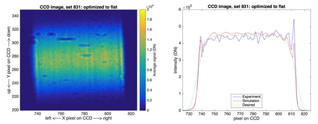
The validation of the simulation means that we can use that simulation as a forward model that describes how the beam shape changes with specific voltages. This was used with a numerical nonlinear optimization code to estimate the voltages that will produce a specific beam profile. Figure 4 shows the results of one experiment, where the diffraction pattern from the pinhole, which produces a ±15% “concave down” profile, is converted to a flat profile. This required a 130-nm root-mean-square height signal on the x-ray deformable mirror surface.
The beam-shaping results were obtained with an “open loop,” or without feedback that measures the x-ray deformable mirror’s actual position. While they represent an important modality for adaptive x-ray optics, to truly close the loop we need metrology of the x-ray deformable mirror surface or the electric field. Our first metrology experiments at the Advanced Light Source used the non-diffractive approach of long-trace profiling, which directly interrogates the slope of the x-ray deformable mirror’s surface. As described in Poyneer,4 these initial measurements were successful, but were not anywhere near precise enough to control the mirror at the nanometer-level.
For high-precision metrology, the best approach was grating interferometry, which has previously been used at x-ray light sources, notably by Rutishauser.5 A special grating made of a 1.9-μm-thick, freestanding membrane of silicon was custom fabricated by Lawrence Berkeley’s Center for X-Ray Optics. This grating, with 3.5-μm wide lines, was specifically designed to allow measurement of up to 11 cycles across the x-ray deformable mirror’s diameter (enough to flatten it to a 1-nm root-mean-square figure). The phase grating produces a fringe pattern at the detector, where the lateral motion of the bright fringes encodes the phase difference. We validated the sensor as deployed, demonstrating that at a 2.5-nm root-mean-square height, the sinusoid was measured at a signal-to-noise ratio of eight, as predicted from the design (Figure 5).
To use the interferometer to control the x-ray deformable mirror, we used an interaction and control matrix approach, where the x-ray deformable mirror itself is used to create the control model. For the closed-loop tests, the mirror was first placed at a known set of voltages (e.g., a sinusoidal figure) and a "reference slope” measurement was taken. Then the voltages were reset and the reference was subtracted from each measurement. In this way the mirror was driven to a shape that presents the same phase error to the grating interferometer.
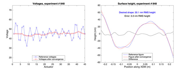
Figure 6 shows the results of placing the x-ray deformable mirror at the voltages that produced the 0.7-nm root-mean-square flat shape (see Figure 1). After loop convergence, the x-ray deformable mirror height, as calculated from voltages, shows that the figure matched to a 3-nm root-mean-square error. Though photon noise is a limiting factor, the main issue for the correction is that the control matrix did not command the x-ray deformable mirror’s mid-range spatial frequencies. The closed-loop operation was at 0.25 Hz. The latency was dominated by 2-s exposures and a 1-s delay because of upstream hardware issues. Computational time was negligible compared to exposure time.
Impact on Mission
Development of the first U.S. capability for adaptive x-ray optics can address broad DOE and Laboratory needs including advanced x-ray optics that may significantly improve beam quality at DOE x-ray light source user facilities such as the Linac Coherent Light Source at the SLAC National Accelerator Laboratory at Stanford and advanced diagnostics for laser-based user facilities such as Livermore’s National Ignition Facility, in support of the Laboratory’s core competency in laser and optical materials. In addition, use of deformable x-ray optics provides a way to correct “thermal bump” figure errors downstream, which would otherwise be expensive and challenging to fully correct at the source with custom cooling systems.
Conclusion
We have developed an integrated and validated understanding of the key components of an adaptive x-ray optics system. We have calibrated and can precisely control our x-ray deformable mirror at the nanometer level, which has successfully been fielded at the Advanced Light Source in an x-ray experiment. The physics-based models of the mirror and experiment are accurate enough that they can be used to precisely control the absolute shape of the x-ray beam in the near field. The grating interferometer measures slope errors at its designed noise level, and has been used to control the x-ray deformable mirror in a closed loop at 0.25 Hz to a level as low as 3-nm root-mean-square figure height error. The mirror's performance is presently limited by photon noise and the control algorithm, which controls only a limited range of spatial frequencies of the x-ray deformable mirror surface. The next step is to use adaptive x-ray optics in a scientific experiment as a demonstration of its value. This could be conducted in the existing setup at the Advanced Light Source, for example, using the x-ray deformable mirror to assist in ptychography measurements used to solve diffraction-phase problems. Alternatively, the x-ray deformable mirror could be tested in a contained experiment at a facility such as the Linac Coherent Light Source, where it would provide a customized beam profile for material studies.
References
- Mimura, H., et al., “Breaking the 10 nm barrier in hard-x-ray focusing,” Nat. Physics 6, 122 (2010).
- Poyneer, L. A., et al., “Sub-nanometer flattening of 45 cm long, 45 actuator x-ray deformable mirror,” Appl. Optic. 53, 3404 (2014).
- Laundy, D., et al., “Surface profiling of x-ray mirrors for shaping focused beams,” Optic. Express, 23, 1576 (2015).
- Poyneer, L. A., et al., “X-ray metrology and performance of a 45-cm long x-ray deformable mirror,” Rev. Sci. Instrum. 87, 052003 (2016). LLNL-JRNL-678726.
- Rutishauser, S., et al., “Exploring the wavefront of hard x-ray free-electron laser radiation,” Nat. Comm. 3, 947 (2012).
Publications and Presentations
- Brejnholt, N. F., et al., Recent results and future plans for a 45 actuator adaptive x-ray optics experiment at the Advanced Light Source. 12th Intl. Conf. Synchrotron Radiation Instrumentation, New York, NY, July 6–10, 2015. LLNL-PROC-674839.
- Poyneer, L., “Control of a 45-cm long x-ray deformable mirror with either external or internal metrology.” Proc. SPIE 9208 (2014). http://dx.doi.org/10.1117/12.2062072
- Poyneer, L., “Sub-nanometer flattening of 45 cm long, 45 actuator x-ray deformable mirror.” Appl. Optic. 53, 3404 (2014). http://dx.doi.org/10.1364/AO.53.003404
- Poyneer, L., “The adaptive x-ray optic project at the Lawrence Livermore National Laboratory.” J. Phys. Conf. 493 (2014). http://dx.doi.org/10.1088/1742-6596/493/1/012022
- Poyneer, L., et al., At-wavelength experiments with a 45-cm long x-ray deformable mirror at the Advanced Light Source. IWXM 2015—International Workshop on X-Ray Optics and Metrology, Berkeley, CA, July 14–16, 2015. LLNL-ABS-669538.
- Poyneer, L. A., et al., “Design and implementation of precise x-ray metrology to control a 45-cm long x-ray deformable mirror,” Proc. SPIE 9965 (2016). LLNL-PROC-701213.
- Poyneer, L. A., et al., “X-ray metrology and performance of a 45-cm long x-ray deformable mirror,” Rev. Sci. Instrum. 87, 052003 (2016). LLNL-JRNL-678726.


