Kevin Baker (15-ERD-064)
Abstract
With this project, we intend to demonstrate high spatial- and temporal-resolution x-ray imaging using optical detectors, and in particular, the VISAR (velocity interferometer system for any reflector) and OHRV (OMEGA high-resolution velocimeter) diagnostics on the OMEGA laser at the Laboratory for Laser Energetics in Rochester, New York. The x-ray source being imaged is a backlighter capsule being imploded by 39 beams of the OMEGA laser. A semiconductor surface facing the backlighter capsule is coated with a thin aluminum layer to allow x rays to pass through the metal layer to be absorbed by the semiconductor. The other side of the semiconductor is coated with anti-reflective material to allow the VISAR or OHRV probe beam to sample the phase change of the semiconductor as the x rays are absorbed in the semiconductor. This technique is capable of acquiring sub-picosecond two- or one-dimensional x-ray images, detector spatial resolution of better than 10 μm, and the ability to operate in a high neutron-flux environment expected on ignition shots with burning plasmas.
In addition to demonstrating this technique on the OMEGA laser, several designs were made to improve the phase sensitivity, temporal resolution, and number of frames over the existing diagnostics currently implemented on the OMEGA laser. These designs included both two-dimensional imaging diagnostics as well as improved one-dimensional imaging diagnostics, which were streaked in time.
Background and Research Objectives
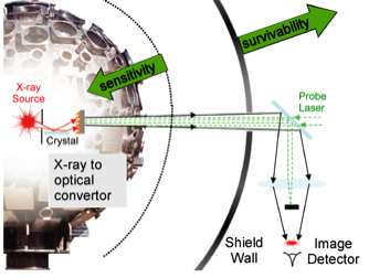
The very short burn time and small size of burning plasmas created at advanced laser-fusion facilities mean that high-spatial-resolution imaging diagnostics with extremely high-time resolution of a few picoseconds will be required for ignited plasma research. These instruments must function in an environment of extremely large neutron fluxes that will cause conventional diagnostics to fail because of radiation damage and induced background levels. A unique new solution to this challenge is to perform an ultrafast conversion of the x-ray signals into the optical regime before the neutrons are able to reach the detector, and then to relay the image signal out of the chamber and into a shielded bunker, protected from the effects of these neutrons, as illustrated in Figure 1.
The goal is to perform an ultrafast conversion of the x-ray signals into the optical regime using the small changes in refractive index produced by the absorption of ionizing radiation in semiconductors. The x-ray image is encoded in, at most, a few picoseconds on an optical probe beam traveling through a 50- to 100-μm-thick semiconductor. The optical beam can be conveniently relayed and imaged to a remote shielded location for recording. The all-optical conversion process involves no electrical devices, so it is highly resistant to electromagnetic pulse effects. Because the signal conversion to optical light is nearly instantaneous, even the effects of neutrons hitting the hohlraum target capsule wall and target positioner should not affect the measurement, and the large effects of neutrons interacting with the chamber and target area are completely avoided. The 1- to 2-ps time resolution possible with this technique is comparable to or better than the fastest electronic devices, the DIXI (dilation x-ray imager) camera or fast streak cameras, and the 5- to 10-μm detector spatial resolution possible is far superior to the approximately 200-μm resolution of the fast electronic DIXI or streak cameras.
Ultrafast picosecond diagnostics based upon these principles can be developed using pulsed or spectrally chirped optical-probe beams to encode gated or streaked x-ray images on an optical probe beam. Multiple time snapshots, short x-ray movies with 4 to 20 frames and picosecond resolution, can be taken from a single line-of-sight by probing the semiconductor with multiple optical beams separated by a combination of probe beam polarization, angle, and wavelength. In addition, it may be possible to make measurements driven by the neutrons from the target at late times close to or even after the neutrons hit the chamber wall with this technique, which could not be done in any other way. Multiple gated images and continuous record (streaked) x-ray data with picosecond time resolution can be recorded without exposing any expensive electronic equipment to the effects of neutron-generated electromagnetic pulse and neutron radiation.
Scientific Approach and Accomplishments
Experiments on the OMEGA Laser
For this research project, our emphasis was on developing changes to existing diagnostics on the OMEGA laser facility at the Laboratory for Laser Energetics to enable demonstration of the concepts described above. That is, to show that x-ray images could be made by imaging an x-ray source onto a semiconductor to create a spatially dependent index-of-refraction change in the semiconductor. This spatially dependent index-of-refraction change could then be detected via an optical instrument such as the VISAR and the OHRV diagnostics at the OMEGA facility.
A total of 39 beams with SG4 phase plates were used to implode a backlighter capsule at the OMEGA facility to create a spatially dependent x-ray source. The 39 beams had a combined energy of 19.5 kJ and utilized a laser pulse shape that was a 1-ns square pulse in time. The backlighter capsule itself was a 9-μm thick, 860-μm-diameter carbon–hydrogen capsule with no fill gas. In addition to the VISAR and OHRV diagnostics, an x-ray framing camera was used to capture two-dimensional images of the imploding backlighter capsule. The camera was located on the ten-inch manipulator #3, the standard interface for target diagnostics, and had a 16-pinhole array with a magnification of 12. The pinholes were 6 μm in diameter with 4-mil beryllium filtering. At about 600 ps, the capsule size is 500 μm in diameter. The capsule size at 1.2 to 1.4 ns is about 250 μm. Peak emission is seen between 1.2 to 1.4 ns.
The x-ray emission from the backlighter capsule was also imaged onto a semiconductor, diamond or quartz, using a miniature x-ray snout, as shown in Figure 2(a). The VISAR then probed the semiconductor from the back and measured the induced phase change inside the semiconductor from the impinging x rays, as shown in Figure 2(b). The Dante soft x-ray diagnostic was also used to measure the spatially integrated x-ray emission from the capsule as a function of time. A comparison between the VISAR and DANTE diagnostics is shown in Figure 2(c). Specifically, a line out of the semiconductor phase change measured by the VISAR is compared to the Dante diagnostic, channel 11.
Detector Designs for Improved Sensitivity and Data Frames
We developed several design changes for the VISAR, OHRV, and similar diagnostics to increase their sensitivity, dynamic range, or frame number to enable them to be more amenable to the function of detecting x rays, as well as replacing the current technology.
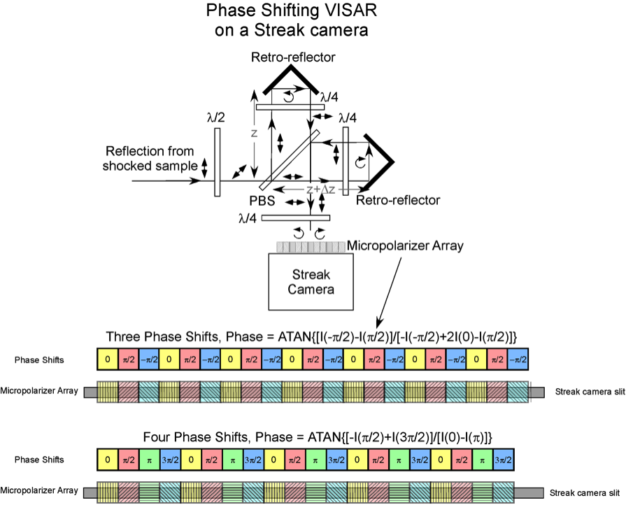
The current VISAR system on OMEGA uses carrier frequency interferometry to determine the phase. An increase of an order-of-magnitude in phase resolution could be achieved by converting the operation to a phase-shifting interferometry mode. The VISAR phase sensitivity for the OMEGA laser is cited as being ~λ/20. The ±0.05 fringe uncertainty applied to the most sensitive velocity per fringe (VPF) (30-mm etalon interferometer with VPF0 = 1.7 km/s fringe−1) indicates that the system detection limit is ~0.09 km/s.1 Using a phase-shifting VISAR approach, a phase sensitivity of better than an order of magnitude could be obtained. This would enable better equation-of-state data to be obtained within the pressure range of interest to Inertial Confinement Fusion. This has a large effect on the peak growth rate of hydrodynamic instabilities in Inertial Confinement Fusion implosions, for example.2
One such phase-shifting design is shown in Figure 3, in which a micro-polarizer array is used. The phase shifts come from the pixel at the measurement location and one or two pixels on either side of the measurement location, depending on the number of desired phase shifts (3, 4, or 5). The micro-polarizer array can be fabricated using lithographic techniques to ensure precise angular rotations and pitch of the polarizing elements. This would most easily be accomplished with a Michelson interferometer employing retro-reflectors, but could also be done with the existing Mach–Zehnder interferometers. The phase-shifting VISAR correctly accounts for background signals and for the amplitudes of the two beams. The phase shifts can also be designed to minimize the sensitivity of the interferometer to detector nonlinearities, for instance, which will be present in the streak camera and charge-coupled device detector, such that it can detect much smaller phase shifts than a carrier frequency interferometer.3 In particular, four phase shifts with a relative π/2 phase shift would be insensitive to quadratic detector nonlinearities, and six phase shifts with a relative π/3 phase shift would be insensitive to detector nonlinearities up to and including the fourth power. Phase-shifting interferometers can easily detect phase shifts of λ/100, with the best systems capable of measurements of better than λ/1,000. This could then provide an increase in accuracy over the current carrier frequency VISAR diagnostics of more than an order of magnitude.
The design could be implemented on the existing OMEGA and on Livermore National Ignition Facility VISAR diagnostics with the addition or substitution of a relatively small number of components. The phase shifting in the interferometer design is accomplished by sending orthogonally circularly polarized beams through a polarizer.4–6 When left-hand and right-hand circularly polarized beams pass through a polarizer at an angle θ, the phase is advanced and retarded by the amount θ, respectively. The overall phase difference between the two electric fields after passing through the polarizer is then 2θ. By rotating the polarizer by θ = 45° between adjacent pixels, the phase difference between the interfering electric fields is increased by 90°.
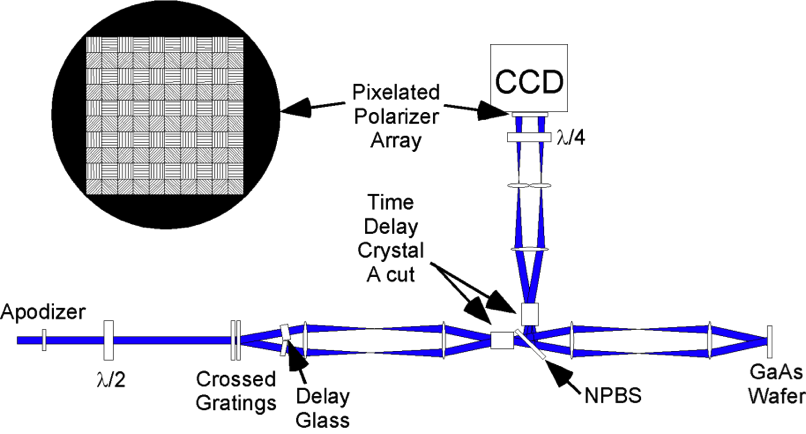
A four-frame, two-dimensional x-ray imager design is shown in Figure 4. This can have more than an order-of-magnitude shorter integration time than gated x-ray imagers, around 1 ps, and up to an order-of-magnitude higher sensitivity than DIXI or the current implementation of OHRV on the OMEGA laser. This imager utilizes a new time-differential interferometer that measures the relative x-ray induced optical phase shifts at two precisely defined time intervals. It operates in a similar manner as an optical VISAR detector; however, our design results in a truly common-path interferometer.7,8 The probe laser enters from the left side and the x-ray source would be imaged onto the gallium arsenide semiconductor from the right-hand side. The probe enters from the left and passes through an apodizer and then through a diffractive optical element to split it into four or more separate probe beams. These separate probe beams then pass through a delay glass array, which puts a different time delay on each of the beams. They then pass through an a-cut crystal (cut along the crystallographic a axis) to provide a set time delay between the two polarizations of each of the four probe beams. They are then imaged onto the semiconductor where the two orthogonal polarizations of each of the probe beams sample the phase of the gallium arsenide semiconductor at two times separated by the delay introduced by the a-cut crystal. The four probe beams are then imaged onto a charge-coupled device after passing through a quarter-wave plate, to make them circularly polarized, and then a pixelated polarizer array, to enable four phase shifts to be measured by the charge-coupled device camera. The result is four frames of data taken at different times along a single line-of-sight with the gate time set by the time delay in the a-cut crystal.
Impact on Mission
Our research into performing ultrafast conversion of diagnostic x rays into the optical regime and relaying the signal out of a test chamber for evaluation of plasmas is important to LLNL's strategic focus in stockpile stewardship science— understanding the physics of high-energy-density plasmas for Inertial Confinement Fusion, stockpile stewardship, and basic astrophysical science. This will be particularly important for studying burning plasmas at Livermore's National Ignition Facility.
Conclusion
We demonstrated that the VISAR and OHRV diagnostics on the OMEGA laser could be made to function as x-ray detectors. Our approach demonstrated that by using the time-differential nature of these diagnostics, the limitation associated with the time response, in particular the fall time, of semiconductors could be overcome to enable them to function as fast x-ray detectors. This technique is capable of acquiring sub-picosecond two- or one-dimensional x-ray images, with detector spatial resolution of better than 10 μm and the ability to operate in a high neutron-flux environment expected on ignition shots with burning plasmas. In addition to demonstrating this technique, several designs were made to improve the phase sensitivity, temporal resolution, and number of frames over the existing diagnostics currently implemented on the OMEGA laser. These designs included both two-dimensional imaging diagnostics as well as improved one-dimensional imaging diagnostics, which were streaked in time.
References
- Celliers, P. M., et al., “Line-imaging velocimeter for shock diagnostics at the OMEGA laser facility,” Rev. Sci. Instrum. 75, 4916 (2004).
- Clark, D. S., et al., "Plastic ablator ignition capsule design for the National Ignition Facility," J. Phys. Conf. 244, 022010 (2010).
- Phillion, D. W., "General methods for generating phase-shifting interferometry algorithms," Appl. Optic. 36, 8098 (1997).
- Baker, K. L., "Interferometric wavefront sensors for high contrast imaging," Optic. Express 14, 10970 (2006).
- Kothiyal, M. P., and C. Delisle, “Shearing interferometer for phase shifting interferometry with polarization phase shifter,” Appl. Optic. 24, 4439 (1985).
- Millerd, J., et al., “Pixelated phase-mask dynamic interferometer,” Proc. SPIE 5531, 304 (2004).
- Baker, K. L., “Interferometric wavefront sensors for high contrast imaging,” Optic. Express 14, 10970 (2006).
- Baker, K. L., and E. A. Stappaerts, “Assessment of a single-shot, pixelated phase-shifting interferometer utilizing a liquid crystal spatial light modulator,” Optic. Lett. 31 733 (2006).


