Philip Datte (17-ERD-032)
Executive Summary
We are combining two mature technologies—a charge-coupled device and a silicon drift detector—to develop a low-maintenance, solid-state streak camera. This technology will support a variety of national missions and has broad application to fields of research that require ultrafast diagnostics, such as high-energy-density physics and astrophysics.
Project Description
Streak detectors or "streak cameras" measure ultrafast light phenomena and provide intensity versus time versus position (or wavelength) information. These systems and their variants are used in high-speed x-ray detection, life sciences, high-intensity x-ray light sources, and astrophysics. The underlying technology and fundamental implementation of these systems have not changed over their 30-year existence. Present-day systems comprise a photocathode material (cesium iodide), an electron tube, a micro-channel plate, a phosphor plate, and a scientific-grade charge-coupled-device camera. Systems require complex, pulsed and direct-current high-voltage power supplies to operate while the cameras need extensive calibration and generation of software correction files. The operational streak window ranges from a few nanoseconds to several tens of nanoseconds with typical time resolution of about 30 ps/pixel and a spatial range of nominally 17-mm aperture. The photocathode material is used for the measurement band of 500 eV to 6 keV, with an average conversion of one electron per x-ray photon, peaking at 1 keV. We are developing a low-maintenance, solid-state streak camera, designed to operate over an x-ray range from 500 eV to ~70 keV. The concept is based on the solid-state drift detector developed for a large-collection area with low equivalent-capacitance configurations that provides large-area coverage and high energy resolution. The voltage supplies are relatively low at ~300 V maximum (typical), and the temporal resolution will be comparable with the existing capability of ~30 ps/pixel.
We expect to demonstrate a fully functional, small-scale implementation of the final streak-camera detector system. The simplest form of streak-detector implementation, recording an input signal placed at the center of the camera recording window, functions much like a simple diode, without using the spatial extent of the cathode. Taking advantage of the cathode's entire spatial extent would demonstrate our camera's real advantage, allowing for simultaneous independent recording of multiple inputs limited only by the resolution element and light cross-talk. This behavior is ideal for coupling a spectrometer's output to the camera's input. The configuration allows for the time-resolved measurement of spectral data with sub-nanosecond resolution. We expect to model, design, fabricate, and test this solid-state streak detector, addressing key developments for advancing high-speed x-ray diagnostic recording systems. Variants of this technology have an equally high impact on scientific disciplines relying on x-ray imaging and high-speed x-ray recording.
Mission Relevance
Our work supports NNSA's goal to strengthen the science, technology, and engineering base. The resultant innovative high-speed x-ray detection capability enhances the Laboratory's high-energy-density science and lasers and optical science and technology core competencies.
FY17 Accomplishments and Results
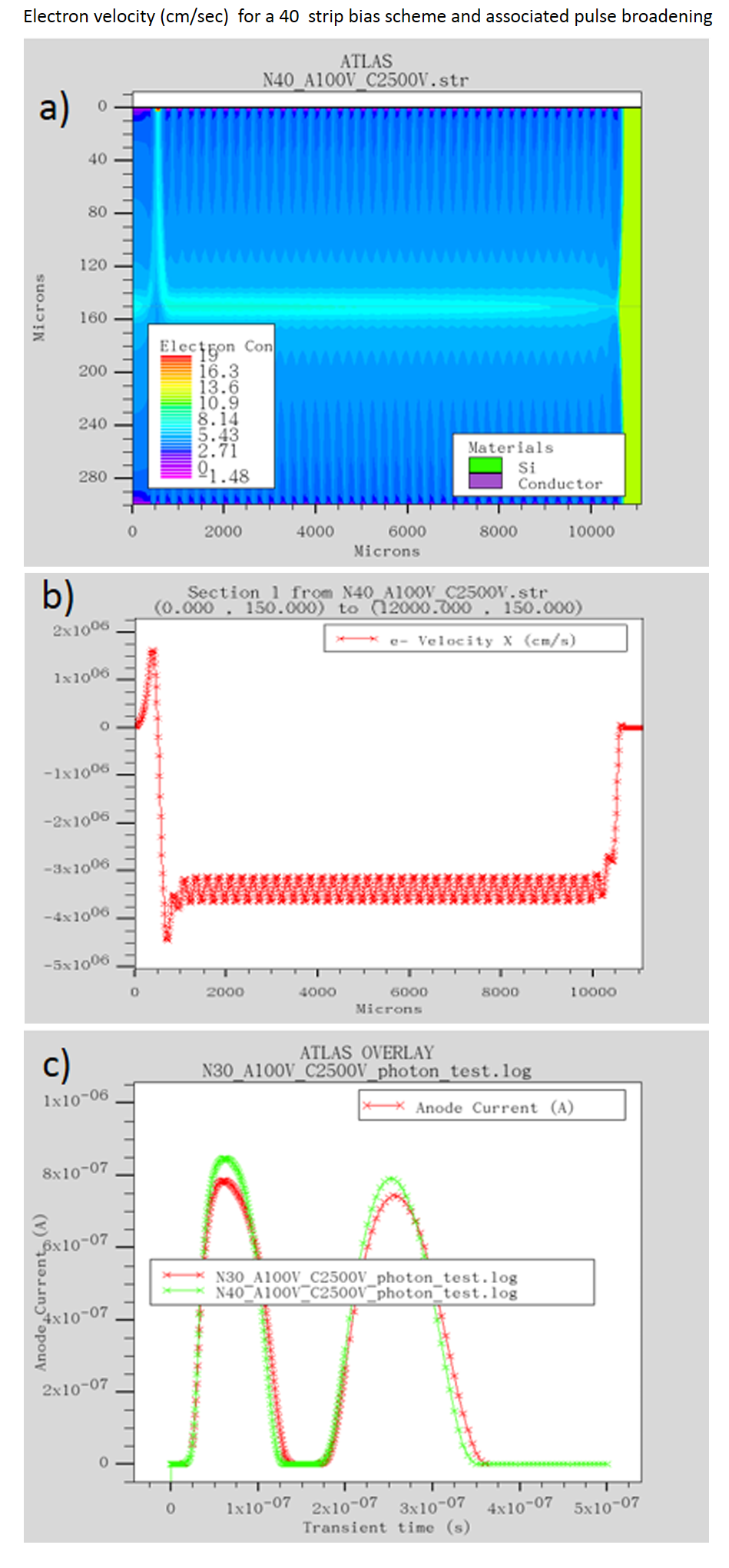
In FY17 we (1) developed a simulation of the solid-state streak detector; (2) designed a nominal 5-mm-long, linear, one-dimensional model to understand the effects of the drift field shaping geometry, long-distance charge transport, diffusion effects, and pulse-shape dispersion; (3) determined that charge can be drifted in the bulk semiconductor material longer than the nominal 25-ns pulse width, with some loss in temporal resolution; (4) observed dispersion, due mainly to gradient intensity and diffusion; (5) and started analysis of diffusion.


