Trevor Willey (14-ERD-018)
Abstract
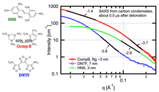
Determining both carbon condensation kinetics and resulting carbon allotropes are fundamental to validating and providing empirical input to detonation models. A variety of carbon allotropes are recovered from detonation soots, with little known experimentally on how quickly, and under what conditions, they form. In this project, we created a capability to perform small-angle x-ray scattering on detonating explosives to observe formation of carbon condensates during detonation. Three explosives were chosen and investigated based on detonation properties. Specifically, HNS (hexanitrostilbene) is known to produce copious graphitic soots with its relatively slow, cool detonation; Composition B (a mixture of 40% trinitrotoluene, or TNT and 60% trimethylenetrinitramine, or RDX) is used to produce detonation nanodiamond, a material with broad technological significance; and DNTF (dinitrofurazanfuroxan) which has a relatively hot and fast detonation. We observed radii of gyration of about 3 nm in both HNS and Composition B, but Composition B produces three-dimensional particles while HNS produces particles of a complex morphology. The DNTF produces much larger three-dimensional particles. All three produce these primary particles over the first few-hundred nanoseconds after detonation, with no changes to the small-angle x-ray scattering profile over subsequent microseconds, in direct contradiction to previous assertions in the scientific literature. The data are also consistent with recovered soots, where Composition B produces significant, approximately 5-nm nanodiamond, DNTF produces large (~10 nm) carbon onions, and HNS produces graphitic carbon in a complex morphology.
Background and Research Objectives
A major hindrance to developing more accurate models for high-explosive detonation is the lack of experimental data for processes occurring at sub-micrometer length scales and on timescales ranging from nanoseconds to microseconds. Many high explosives consist of carbon, hydrogen, nitrogen, and oxygen, and are often referred to as CHNO explosives. Products of CHNO explosive detonations are primarily gaseous nitrogen, water carbon dioxide, and carbon monoxide, but excess carbon also condenses during detonation, ultimately producing solid nanometer-scale carbon materials. The carbon condensate allotrope (i.e., graphitic and diamond-like) and the particle growth kinetics are not well known nor easily measured. In particular, detonation phenomena at these time and length scales are not amenable to measurement because of the optical opacity at the detonation front. Our research objective was to develop a capability to measure carbon condensation using time-dependent, small-angle x-ray scattering. Initial experiments focused on HNS (hexanitrostilbene), and Composition B, a mixture of 40% TNT (trinitrotoluene) and 60% RDX (hexogen or trimethylenetrinitramine). In addition, we investigated DNTF (3,4-dinitrofurazanfuroxan), an explosive that produces fast and relatively hot detonations. These three span temperature and pressure conditions one might expect in detonations of conventional CHNO explosives. The HNS detonations are relatively cold, slow, and produce copious graphitic soots. Composition B is an intermediate explosive in temperature and pressure compared to the other two and is known to produce nanodiamond. The DNTF is an explosive that produces very hot conditions that theoretically should produce liquid carbon droplets for the first few hundred nanoseconds. We were able to observe dramatically differing morphologies as these particles form during detonation using small-angle x-ray scattering, and also recovered and analyzed soots from the three explosives. We found that carbon nanoparticulates form on timescales of several tens to hundreds of nanoseconds, rather than over microseconds as previously asserted.1–3
Scientific Approach and Accomplishments
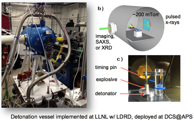
Our goal with this project was to measure carbon condensate morphology and formation kinetics during high-explosive detonation. To this end, we developed a capability to perform small-angle x-ray scattering, radiographic imaging, and potentially x-ray diffraction during detonation. Figure 1 presents details of the experimental setup. Samples were fixed on top of a detonator. The top of the explosive has a spring-loaded piezoelectric timing pin (Dynasen.) The assembly was attached to a two-axis motion stage and installed within an approximately 120-L steel vacuum tank (Teledyne RISI) mechanically designed to fully contain up to 10-g detonations, shown in Figure 1(a). The tank was modified with entrance and exit windows to minimize x-ray attenuation and extraneous scattering during small-angle x-ray scattering experiments, yet preserve vacuum and contain shrapnel. Typically, base pressures were greater than 200 mTorr just prior to detonation. The pressure rises to a several torrs after detonation in the sealed vacuum chamber from the created product gasses.
Time-resolved small-angle x-ray scattering experiments were performed at the Dynamic Compression Sector at the Advanced Photon Source, Argonne National Laboratory, within the special-purpose hutch (35-ID-B). This insertion device beam line offers very high flux to a suite of state-of-the-art platforms for materials science under extreme conditions (e.g., shock physics4,5). A focused pink beam, operating in 24-bunch mode, was selected for most of these experiments with a nominal energy of 23.6 keV or 14.5 keV and spot size of approximately 200 × 50 μm, pulse periodicity of 153.4 ns, and pulse durations of less than 100 ps. Scattering intensity was recorded as described elsewhere.1,4,5
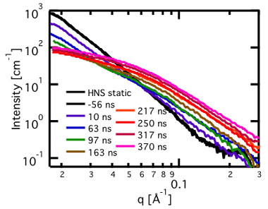
Figure 2 shows representative time-resolved small-angle x-ray scattering patterns for HNS from three time-interleaved shots acquired during 24-bunch (153.4-ns) mode. The black trace is of undetonated HNS and is indicative of the much larger, micrometer-scale voids because this is a power law with no obvious Guiner knee (analysis technique of the scattering curve at very lowest scattering angles) at our lowest measurable scattering angles (~2 × 10⁻² Å-1).1 As the detonation front passes through the measurement point, this void structure diminishes from the traces over the first approximately 100 ns and evolves into the small-angle x-ray scattering pattern from the resultant soot. In the case of HNS, the soots form much more rapidly than anticipated based on previous results on similar explosives.2,3 Generally, primary-particle soots form within the first few hundred nanoseconds in all explosives measured with this instrument thus far, on detonations ranging from 400-mg, 6-mm-diameter HNS and DNTF, and 2-g , 9.5-mm-diameter HNS, DNTF, Composition B, PBX (polymer bonded explosive) 9501, TNT and RDX mixtures, and overdriven PBX-9502.
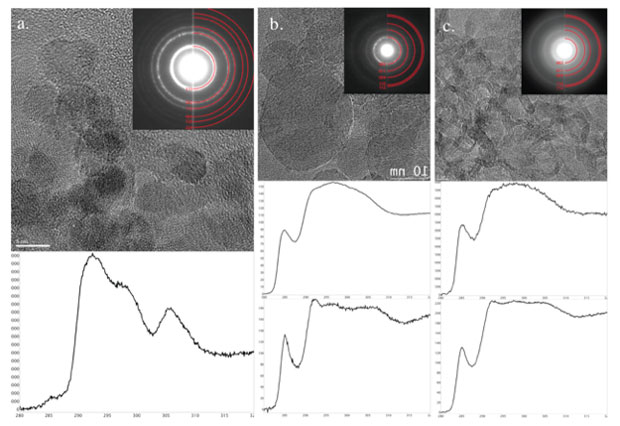
Analysis of recovered soots provide additional information to compare with kinetic data. Explosives of similar size were detonated in aluminum vessels containing an ice capture layer. The capture layer was formed by filling the vessels with de-ionized water, and freezing the vessel while maintaining a 13-mm diameter cylindrical bore. Explosive charges with outer diameter of 9.52 mm were then detonated deeply within the bore. Post-detonation, soots were recovered from the ice/slush capture layer. Aliquots of recovered soots were taken from the collection vessels and drop cast on 8-nm thick silicon nitride transmission election microscopy membranes (Ted Pella, Inc.). Transmission electron microscopy analysis was performed on a JEOL 2100F field-emission microscope operating at 200 kV. Images and diffraction patterns were acquired with an Orius SC1000 CCD at 1× binning, and electron energy-loss spectroscopy spectra were collected with a Gatan Tridiem spectrometer using a dispersion of 0.1 eV. Observable beam damage to the samples occurred only when the beam was left stationary for a prolonged time, many tens of seconds, while operating in the mode of scanning transmission election microscopy.
Transmission electron microscopy images, electron diffraction, and energy-loss spectroscopy spectra from Composition B, DNTF, and HNS are shown in Figure 4. Composition B (Figure. 4) contains about 5-nm-sized particles. Energy-loss spectroscopy and diffraction both show these particles in this local field of view are overwhelmingly diamond. The DNTF, the hottest and fastest detonation, forms about 10-nm carbon structures with concentric graphitic shells, colloquially known as carbon "onions," that are often apparently hollow. Spectroscopy, with a strong pi* atomic electronic peak, as well as diffraction lines show these structures are graphitic or sp2 hybridized orbital carbon. Finally, HNS produces a complex ribbon- and rod-like leafy structure, and also is highly graphitic. Interestingly, the time-dependent small-angle x-ray scattering, at timescales later than a few hundred nanoseconds are consistent with the morphology of the recovered soots, indicating that the primary soot particles form very rapidly. The DNTF is a particularly interesting case—at early times, theory predicts temperatures and pressures well into liquid carbon over the first few hundred nanoseconds. We see a stark change in scattering that is consistent with timescales when a liquid–solid phase transition would be expected. These data, however, cannot unequivocally discount an intermediate diamond phase. First, nanodiamonds transition to carbon onions under heating or high electron flux. Second, vacuum detonation conditions for small-angle x-ray scattering are not identical to atmospheric or ice detonations. At late times, however, the recovered carbon onions are very consistent with small-angle x-ray scattering from a few hundred nanoseconds to several microseconds, suggesting the pathway for these particles may be solidification of liquid carbon directly to carbon onions.
Impact on Mission
Stockpile stewardship, counterterrorism efforts, and the design of advanced conventional munitions will directly benefit from our efforts to understand the fundamental processes of dynamic compression and collapse of voids for hot-spot formation and the carbon condensation and associated energy release behind explosive detonation fronts. Exploring the behavior of energetic materials during detonation also aligns with the Laboratory's core competency in advanced materials and manufacturing. Stockpile Stewardship depends upon accurate modeling of various phenomena, including detonation— such detonation modeling requires experimental validation. Thermochemical codes such as Cheetah aim to predict, for example, detonation velocity to high precision. Up to 10% of the energy released during detonation is thought to be because of carbon precipitation behind detonation fronts. The work benefits fundamental materials science by exploring conditions that lead to detonation nanodiamond formation, a widely used material in seeding synthetic diamond growth and used in various biotechnological applications. Finally, a refined understanding of detonation phenomena potentially benefits counterterrorism and counterproliferation efforts, as well as design of advanced conventional munitions.
Response of materials from atomic to macroscopic length scales and timescales of nanoseconds to microseconds are central to stockpile stewardship. Our research is now evolving into a broader mesoscale detonation science portfolio that could eventually use facilities such as MaRIE (Matter–Radiation Interactions in Extremes.) For the near-term future, our project developed capabilities that have evolved into several efforts regarding detonator surveillance and detonator development through imaging of functioning exploding foil initiator slapper detonators, an NNSA funded project directly supporting detonation model development, and a new NNSA project investigating detonation soots from common explosives. The two NNSA-related projects compare and contrast soot formation during conventional versus overdriven detonation. Finally, during the course of our project, we have developed strategic collaborations and partnerships with Los Alamos National Laboratory and The Dynamic Compression Sector at Argonne National Laboratory.
Conclusion
In conclusion, we have developed a capability for acquiring small-angle x-ray scattering and/or radiographic images from detonation events. In a series of three explosives, HNS rapidly produces graphitic soots with a complex morphology. Composition B produces three-dimensional particles with radius of gyration of about 3 nm. Recovered soots contain copious nanodiamond particles of 5 to 6 nm. Finally, DNTF soots produce three-dimensional particles at times up to a few hundred nanoseconds, and exhibit a change in the small-angle x-ray scattering and thus morphology at about this time. Late-time recovered soots consist of large, approximately 10-nm carbon onion structures with graphitic character. Such data can now be used to assist in both validating detonation models as well as bounding late-time energy release by understanding the allotropes of carbon produced and the timescales under which they form. Moving forward, this capability will be used to investigate carbon condensation under overdriven conditions, and will be used for imaging of detonation phenomena for a variety of core Lawrence Livermore programs.
References
- Bagge-Hansen, M., et al., “Measurement of carbon condensates using small-angle x-ray scattering during detonation of the high explosive hexanitrostilbene.” J. Appl. Phys. 117(24), 245902 (2015).
- Ten, K. A., E. R. Pruuel, and V. M. Titov, “SAXS measurement and dynamics of condensed carbon growth at detonation of condensed high explosives.” Fullerene. Nanotube. Carbon Nanostruct. 20(4–7), 587 (2012).
- Ten, K. A., et al., “Measurements of SAXS signal during TATB detonation using synchrotron radiation.” 14th Intl. Detonation Symp., Coeur d'Alene, Idaho, Apr. 11–16, 2010.
- Jensen, B. J., et al., “Dynamic experiment using IMPULSE at the Advanced Photon Source.” J. Phys. Conf. Ser. 500(4), 042001 (2014). http://dx.doi.org/10.1088/1742-6596/500/4/042001
- Gupta, Y. M., et al., “Real-time high-resolution x-ray diffraction measurements on shocked crystals at a synchrotron facility.” Rev. Sci. Instrum. 83, 123905 (2016). http://dx.doi.org/10.1063/1.4772577
- Bastea, S., and L. Fried, “Chemical equilibrium detonation.” Shock Wave Science and Technology Reference Library, vol. 6 (F. Zhang, ed.). Springer Publishing Co., New York, NY (2012).
- Viecelli, J. A., et al., “Phase transformations of nanometer size carbon particles in shocked hydrocarbons and explosives.” J. Chem. Phys. 115(6), 2730 (2001).
- Greiner, N. R., et al., “Diamonds in detonation soot.” Nature 333(6172), 440 (1988).
- Kruger, A., et al., “Unusual tight aggregation in detonation nanodiamond: identification and disintegration.” Carbon 43(8), 1722 (2005).
- Danilenko, V. V., “On the history of the discovery of nanodiamond synthesis.” Phys. Solid State 46(4), 595 (2004).
Publications and Presentations
- Willey, T., et al., "Measurement of carbon condensates using small-angle x-ray scattering during detonation of high explosives." AIP Conf. Proc. 1793, 030012 (2017). LLNL-ABS-666422. http://dx.doi.org/10.1063/1.4971470
- Willey, T., "Measurement of carbon condensates using small-angle x-ray scattering during detonation of the high explosive hexanitrostilbene." J. Appl. Phys. 117 (2015). LLNL-JRNL-666850. http://dx.doi.org/10.1063/1.4922866
- Willey, T., et al., "X-ray Imaging and 3D reconstruction of in-flight exploding foil initiator flyers." J. Appl. Phys. 119, 235901 (2016). LLNL-JRNL-670442.


