Michael Messerly (14-ERD-070)
Abstract
Optical fibers have become increasingly important not only for telecommunications, but also for high-power lasers. Fiber lasers are efficient, compact, and robust and have applications in missile defense, medicine, and guide-star lasers, as well as high-flux, laser-based particle accelerators. Today, nonlinear propagation artifacts and thermal instabilities limit beam-combinable fiber lasers to average powers of 3 kW and pulse-transport fibers to energies of a few millijoules, both insufficient to meet long-term, directed-energy needs. Anti-resonant tube fibers and hollow air-guided fibers might extend these limits, but require novel waveguide designs and refined fabrication techniques. We report on two new waveguide designs, one that incorporates both anti-resonant and resonant tubes that sidestep certain fabrication issues and the other that extends the anti-resonant tube concept to all-glass fibers and thus allows for new bend-tolerant laser fibers. We also report fabrication techniques that enable the high-yield fabrication of hollow photonic crystal canes, the precursors to hollow optical fibers, and report on our limited success in drawing these canes into hollow waveguides.
Background and Research Objectives
During their first 40 years, optical fibers were used almost exclusively in telecommunications systems, but over the past ten years they have become increasingly important for high-power lasers, as detailed in Richardson (2010).1 Fibers have a large surface area relative to their enclosed volume and thus dissipate the heat generated by the lasing process (roughly 50 W of heat per kilowatt of power) efficiently. Moreover, if designed and fabricated properly, the waveguide cores integral to a fiber allow it to emit a diffraction-limited beam. With an appropriate beam director, such beams can be brought to a tight focus over hundreds of meters, essential for certain scientific and directed-energy applications. In addition, if co-phased, the beams from many diffraction-limited lasers can be combined into a single diffraction-limited beam, proportionally increasing the net power that fibers can achieve, as described in Redmond (2011)2 and Yu (2012).3
To ensure that fibers propagate diffraction-limited beams, the diameter of a core and thus the diameter of its guided mode must be made small, leading unfortunately to high intensities. The size depends on several factors, but today ranges from ten to one-hundred times the wavelength of the guided light (10–100 µm). At high powers and pulse energies, fibers having mode diameters on the small end of the range are prone to nonlinear propagation artifacts and those having modes on the large end are limited by thermal instabilities; thus, different applications require different fibers. For today’s optimal high-power lasers, the mode diameter is typically 20–25 µm, allowing the fibers to produce 3 kW of diffraction-limited beam-combinable power before the onset of stimulated Brillouin scattering or modal modulation instabilities. For today’s optimal high-pulse energy lasers, where heat dissipation is not an issue but nonlinear propagation artifacts are, the mode diameter generally ranges from 50 µm to 100 µm, which allows the fibers to produce 1–5 mJ pulses. Many Department of Defense and Department of Energy applications require more power or energy, and thus the need for fibers that guide larger modes.
Larger mode sizes usually require smaller differences between the refractive index of the waveguide core and the index of its surrounding cladding. Today’s commercial laser fibers typically have an index difference of 0.0008, just three times the index difference between air and vacuum. As Kong (2016)4 describes, such a small difference is difficult to manufacture repeatably and makes the fibers susceptible to bend-induced losses. Moreover, since the waveguide’s operating temperature can rise 200˚C or more, thermal changes in index can exceed the small manufactured difference, resulting in poor guiding that further limits the laser’s power.
While scaling to higher powers and pulse energies seems to require larger core sizes and commensurately smaller index differences, such fibers have proven to be challenging to manufacture and deploy. The objective of this project was to investigate alternative fibers and designs that would allow higher powers and pulse energies without requiring index control better than 2.8 × 10−⁴, the index difference between air and vacuum, which is near today’s manufacturing limit.
Scientific Approach and Accomplishments
Modeling. This research stems in part from earlier theoretical work we conducted on fibers that support so-called patterned modes, which may allow large mode sizes without the need to control a fiber’s refractive index profile to extremely tight tolerances (that is, to less than 2.8×10−⁴). Qualitatively, as a preferred mode is made larger, its phase velocity tends toward the velocities of unwanted modes, leading to problematic instabilities. Quantitatively, we know that waveguides tend to be bound by an area-spacing product, Θ:where n₁ and n₂ represent the effective phase indices of a preferred mode and a neighboring mode, A₁ is the cross-sectional area of the preferred mode, and λ is the wavelength of the guided light. Models show that for nearly all guides, including step index designs, common variants on the step-index design, and most photonic crystal fibers, Θmax falls between 0.29 and 0.34. Assuming refractive index control of 2.8 × 10−⁴, then mode instabilities become important when the mode area reaches 420 µm² or equivalently, a diameter of 23 µm – roughly what experiments now show.
Modes with certain internal resonant structures can increase the area-spacing product, Θmax, by a factor of 3.2, perhaps increasing the threshold power for modal instabilities by the same factor. At the start of this LDRD, however, we did not have sufficient control of the refractive index of the rare-earth-doped materials required to make the requisite resonant structures, and focused instead on the problem of transporting energetic pulses of light via hollow fibers. (Over the past three years, with funding from other sources, we have gained index control of rare-earth-doped materials to < 2.8 × 10−⁴).
Today the dominant hollow fiber designs are so-called Kagome fibers [these, as described by Wang (2011)5 ], are named for a type of woven bamboo basket, whose pattern this fiber approximates), negative curvature fibers such as those described in Pryamikov (2011),6 and the anti-resonant tube fibers that were first proposed in Kolyadin (2013).7 As part of this project, we fabricated or attempted to fabricate roughly 10 Kagome fibers (see below). However, we did not devote significant resources to modeling these because the shape and size of the beads of glass that form at the structure’s nodes are difficult to reproduce, making the fiber’s properties difficult to correlate to measurements (advice from the University of Bath). However, we did devote resources to modeling negative-curvature and anti-resonant tube fibers, and here focus on progress in the latter.
In anti-resonant tube fibers, hollow tubes having an optical thickness that is approximately mλ/4, where λ is the wavelength of the guided light and m is an odd integer, surround a central hollow guiding region. Such structures do not guide light by total internal reflection but by trapping the light inside the guiding region; importantly, the structures do not touch, thus avoiding the beads of glass that complicate Kagome fibers. Models suggest that the loss of an anti-resonant tube fiber can be less than 0.01 dB/m, making them applicable to transporting high powers over tens of meters (for example, Department-of-Defense–class lasers within an aircraft) or energetic pulses over a few meters (tissue-ionizing-class pulses within an operating room).
Anti-resonant fibers have their own manufacturing challenges: the internal tubes sometimes release from the inner wall of the encapsulating tube during the draw process, or are easily over-expanded causing them to touch. Both make the fibers unusable. Our models show, however, that adding an interior resonant tube to the design, one whose wall thickness is mλ/4 where m is an even integer, also yields low-loss fibers. Moreover, the inner tube might simplify the fabrication process, helping to keep the outer tubes pressed against the encapsulating tube and fixing them in place so they do not touch.
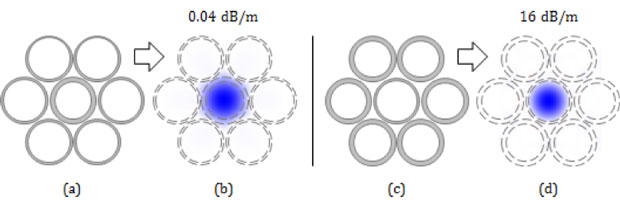
Figure 1 shows that the losses of the fiber having a quarter-wave inner tube are significantly higher than those for the fiber having a half-wave inner tube. However, these calculations are based on models of fibers having an index contrast that is roughly one-tenth the contrast of a true hollow fiber, to keep the finite element mesh from becoming unwieldy. As the index contrast rises, we expect the losses of both to improve (to be verified with experiments).
Unfortunately, the central tube has not yet been shown to simplify the fabrication process, as discussed below. As the fabrication effort proceeded, we modeled the possibility of fabricating anti-resonant fibers via an all-glass structure. These would have no internal air holes, greatly simplifying the fabrication process, and the central guiding region could be doped with rare-earth ions to allow the fiber to serve as an amplifier or laser. An all-glass structure would require a preform having a custom ring-like refractive index profile, but several suppliers (such as Draka/Prysmian of Eindhoven, The Netherlands) can fabricate these using telcom-developed vapor-deposition techniques.
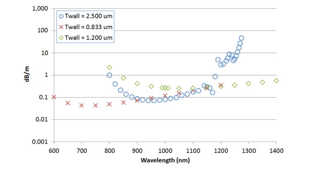
Figure 2 describes the design of the all-solid anti-resonant tube fiber and shows the expected loss versus wavelength. Designs having tubes that are 1 and 5 quarter-waves thick both result in losses less than 0.1 dB/m at 1,000 nm. This fiber supports a relatively large mode of 30-µm diameter; a comparable step-index fiber would only have an index contrast of 5 × 10−⁴, just twice the index difference between air and vacuum. However, since the high index contrast of the anti-resonant tubes is 600-times larger, the mode guided by the ART fiber is more stable and is 2–4 times more bend tolerant.
Fabrication. At the start of the project, a researcher from our group spent two weeks at the University of Bath, a leader in this field, to learn their technique for fabricating hollow fibers. The collaboration took us far along the learning curve, but due to differences between our equipment and theirs, as well as differences in our objectives—our goal is to fabricate long lengths of fibers that reliably withstand extreme powers and pulse energies while their goal is to devise and study novel fibers—much work remained.
Following the method taught by Bath, the basic steps for creating a hollow fiber are to design the waveguide (see discussion above) and then to fabricate the fiber as follows:
- Draw hollow capillaries, typically 1–15 mm in diameter, from larger tubes, typically 34 × 38 mm in diameter.
- Stack the capillaries into the modeled arrangement and insert the array into an encapsulating tube to create a first preform.
- Draw the preform of Step 2 into a 3–10-mm cane.
- Insert the cane of Step 3 into a new tube to form a second preform, and draw the preform into fiber while applying two slight pressures to the cane: one pressure to the central hole and a slightly different pressure to the holes that surround it.
Bath highlighted two precautions: first, the array of Step 2 must fit very tightly into its encapsulating tube to ensure that when the preform is drawn into cane, all nodes in the array melt together where they meet; second, the cane of Step 3 must be drawn at very cold temperatures to prevent the capillaries from collapsing even slightly and thus separating the capillaries before their meeting points fuse. If both conditions are not met, large holes open when the cane is drawn, ruining the fiber.
We encountered many hiccups when implementing the Bath process at our laboratory. Foremost was that the cold temperatures required to hold capillaries open in Step 3 (1700–1750°C) required very large pulling forces and destroyed two motors in our system’s cane puller, losing the motor and two weeks of time for each. A second problem was that our system’s laser micrometer could not measure canes larger than 3 mm, making it difficult to assemble fixtures for applying different pressures inside the canes of Step 4. A third problem is that Steps 3 and 4 require sealants that can handle the temperatures above the drawing furnace, which range from 100°C to 300°C.
We overcame the first problem as follows. To allow for higher draw temperatures for Step 3 and thus to reduce the required pulling forces, we modified the technique by first drawing a small amount of glass from one end of the preform at temperatures of roughly 1800°C. Though the capillaries on this end collapse considerably, they remain large enough so that when we invert the preform and apply slight pressure to the first-drawn end while drawing canes from its opposite end, the canes from that end are perfect; that is, their nodes touch and seal together at all points, with 100% yield.
We overcame the second problem, limited capillary size, by purchasing a larger laser micrometer. This allows for canes as large as 12 mm, four times our original limit, which allows stainless steel hypodermic needles to be placed at appropriate pressure ports on the cane. (The smaller micrometer requires the insertion of delicate glass capillaries because even the smallest hypodermics are too large.)
We overcame the third problem, the need for heat tolerant sealants with proper pre-cure flow characteristics, by trial and error, experimenting with more than a dozen sealants, including ultraviolet-cured acrylates, thermally cured epoxies, and one-part and two-part silicones. We found that one-part temperature-rated silicones, such as those manufactured by 3M and Momentive, meet these requirements. With help from the NIF safety team, we showed that these materials do not outgas harmful or noxious vapors when heated to 300°C.
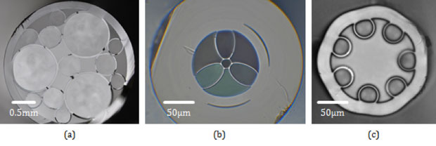
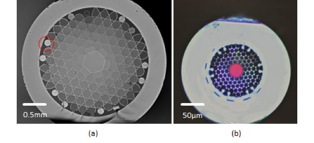
Figure 3 shows a Kagome cane and a Kagome fiber; the fiber was not drawn from the cane shown but a similar one (the cane shown illustrates the challenge of sealing the cane’s nodes). Figure 4 shows a cane having both anti-resonant and resonant tubes, fiber drawn from that cane, and fiber drawn from a cane that has only anti-resonant tubes.
The fibers shown here, as well as others not shown, suggest great promise; the process is now routine until the final step, drawing canes into fiber, at which point the yield is roughly one in five. Unfortunately, none of these could be drawn with sufficiently low loss (<10 dB/m) to allow for testing at high powers or high pulse energies.
Impact on Mission
Successes in the first year of research led to a two-year, DARPA-sponsored project to develop a novel, neutrally buoyant fiber. The work also led to the design of new fibers, resulting in a joint proposal with the Air Force Research Laboratory that was funded in January 2017. The work has also led to funding to develop an anti-resonant tube fiber for a local commercial laser manufacturer, work that should begin in February of 2017 pending DOE contract approval. In the long term, we expect that this research will lead to a safe, vibration-insensitive conduit of extreme light from a centrally located laser to a target or beam, in support of the Laboratory's national security and defense missions.
Finally, this work led to the training of new program staff, including three technicians new to the group, and a post-doctoral student who has been added to Livermore permanent staff since this project began.
Conclusion
This project led to many successes, but unfortunately we cannot yet reliably fabricate hollow fibers to transport multikilowatt or multi-millijoule beams due to the difficulty of applying and controlling pressures on the order of 0.1kPa/0.02psi to two or three (for some fibers) pressure ports as intermediate canes are drawn to 200-µm fibers. We have, however, mastered all steps of the multi-day fabrication process up to this final step, leading to programmatic success in other areas.
References
- Richardson, D. J., J. Nilsson, and W. A. Clarkson, "High power fiber lasers: current status and future perspectives." J. Opt. Soc. Am. B 27, B63 (2010).
- Redmond, S., et al., “Diffractive coherent combining of a 2.5kW fiber laser array into a 1.9kW Gaussian beam.” Optic. Lett. 37, 2832 (2012).
- Yu, C., et al., "Coherent combining of a 4 kW, eight-element fiber amplifier array." Optic. Lett. 36, 2686 (2011).
- Kong, F., et al., "Large-mode-area fibers operating near single-mode regime." Optic. Express 24, 10295 (2016).
- Wang, Y. Y., et al., "Low loss broadband transmission in hypocycloid-core Kagome hollow-core photonic crystal fiber." Optic. Lett. 36, 669 (2011).
- Pryamikov, A. D., et al., "Demonstration of a waveguide regime for a silica hollow-core microstructured optical fiber with a negative curvature of the core boundary in the spectral region > 3.5 μm." Optic. Express 19, 1441 (2011).
- Kolyadin, A. N., et al., "Light transmission in negative curvature hollow core fiber in extremely high material loss region." Optic. Express 21, 9514 (2013).


