Tayyab Suratwala (14-ERD-042)
Abstract
In this project we have developed a detailed understanding of the chemical and mechanical microscopic interactions that occur during polishing and affect the resulting surface microroughness of the workpiece. Through targeted experiments and modeling, the quantitative relationships of many important polishing parameters and characteristics that affect surface microroughness have been determined. These behaviors and phenomena have been described by a number of models, including (a) the Ensemble Hertzian Multi-Gap (EHMG) model, used to predict the removal rate and roughness at atomic-force-microscope-scale lengths as a function of various polishing parameters; (b) the Island Distribution Gap (IDG) model, used to predict the roughness at larger scale lengths; (c) the Deraguin–Verwey–Landau–Overbeek (DVLO) three-body electrostatic colloidal model, used to predict the interaction of slurry particles at the interface and roughness behavior as a function of pH; and (d) a diffusion/chemical reaction rate model of the incorporation of impurities species into the polishing surface layer (called the Beilby layer). Based on this improved understanding, novel strategies to polish the workpiece have been developed simultaneously, leading to both ultrasmooth surfaces and high material-removal rates. Some of these strategies include (a) use of narrow particle-size-distribution slurries, (b) a novel diamond-conditioning recipe of the lap to increase the active contact area between the workpiece and lap without destroying its surface figure, (c) proper control of pH for a given glass type to allow for a uniform distribution of slurry particles at the interface, and (d) increase in applied load just up to the transition between molecular to plastic removal regime for a single slurry particle. These techniques have been incorporated into a previously developed finishing process called convergent polishing, which has led to an economical finishing process with improved surface figure control and simultaneously to a low-roughness surface with high removal rates.
Background and Research Objectives
The past decade has seen significant advancement in optical finishing science, including improving the macroscopic aspects (e.g., overall surface figure) and reducing isolated imperfections (e.g., scratches). At the start of this study in FY14, much less was understood regarding the microscopic-scale length interactions that occur during polishing, specifically those influencing the microroughness and power spectra of the surface. The ability to fabricate very low roughness (2–4 Å rms) surfaces has been around since the 80’s; however, these polishing techniques were derived from an artisan approach, and the processes are very time consuming and expensive. Low-roughness and low-power spectra surfaces are highly desired for high-end x-ray optics, high-fluence laser optics (such as for the National Ignition Facility), and telescope optics to reduce laser beam contrast and to minimize optical scatter.
The two basic objectives of this study have been achieved: to (1) gain a scientific understanding of the microscopic and chemical interactions that occur during polishing and how they influence the microroughness of glass surfaces and (2) develop novel, cost-effective methods to achieve very low roughness on optical glass surfaces both after polishing and post-processing.
Scientific Approach and Accomplishments
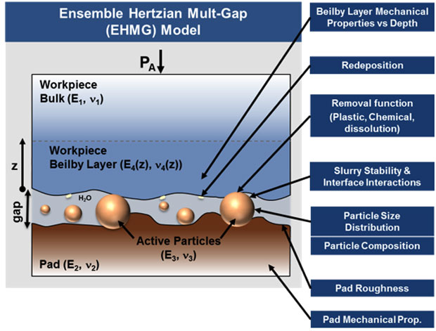
Our approach was to investigate a number of proposed parameters and interactions that can occur at the polishing interface that likely affect the workpiece roughness (Figure 1). Each of these was investigated in detail. These interactions were grouped into four major areas, which are described below.1. Beilby Layer Studies
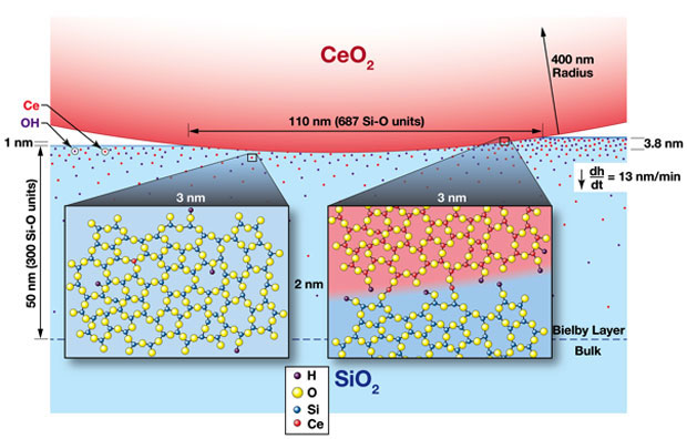
During polishing, the final surface of the workpiece consists of an outer surface layer (tens-of-nanometers thick) that has been modified both chemically and mechanically. Historically, this surface layer has been referred to as the Beilby layer. The mechanism for its creation has been widely debated: Is it a redeposition or a result of diffusion plus reaction effects? In this part of the study, the chemical characteristics and the proposed formation mechanisms of the Beilby layer on polished fused-silica glasses were determined. Fused-silica glass samples were polished using different slurries, polyurethane pads, and at different rotation rates. The concentration profiles of several key contaminants such as cerium, potassium, and hydrogen were measured in the near-surface layer of the polished samples using secondary ion mass spectroscopy. The penetration of potassium, originating from potassium hydroxide used for pH control during polishing, decreased with increase in polishing material removal rate. In contrast, penetration of cerium and hydrogen increased with increase in polishing removal rate. The resulting potassium concentration depth profiles were described using a two-step diffusion process: (1) steady-state moving boundary diffusion (due to material removal during polishing) followed by (2) simple diffusion during ambient post-polishing storage. On the other hand, the observed cerium profiles are inconsistent with diffusion-based transport. Rather, we proposed that cerium penetration is governed by the ratio of cerium–oxygen–silicon and silicon–oxygen–silicon hydrolysis rates, where this ratio increases with interface temperature (which increases with polishing material removal rate), resulting in greater cerium penetration into the Beilby layer. These new insights into the chemistry of the Beilby layer, combined with details of the single-particle removal function during polishing, are used to develop a more detailed and quantitative picture of the polishing process, the formation of the Beilby layer, and surface roughness (see Figure 2).2
2. Removal Function Studies
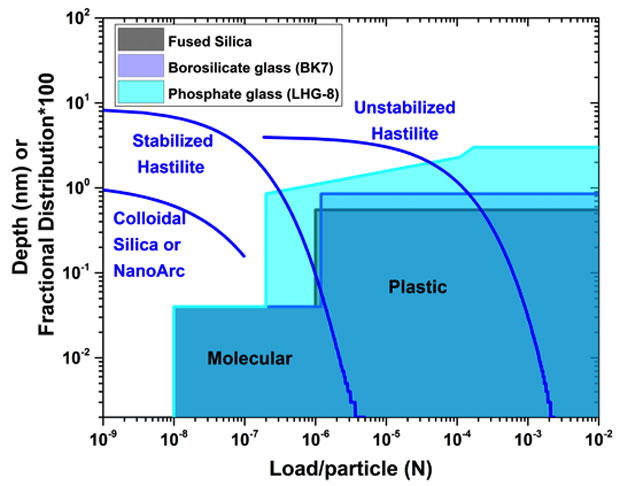
In this part of the study, the nanomechanical deformations on glass surfaces near the elastic–plastic load boundary have been measured on various glasses by nanoscratching using an atomic force microscope to mimic the mechanical interactions of polishing particles during optical polishing.3 Nanoscratches were created in air and aqueous environments using a 150-nm radius diamond-coated tip on polished fused silica, borosilicate, and phosphate glass surfaces; the topology of the nanoscratches were then characterized by atomic-force microscopy. Using load ranges expected on slurry particles during glass polishing (0.05–200 μN), plastic-type scratches were observed with depths in the nanometer range. Nanoscratching in air generally showed deeper and narrower scratches with more pileup compared to nanoscratching in water, especially on fused-silica glass. For phosphate glass, the load dependence of the removal depth was consistent with that expected from Hertzian mechanics. However, for fused-silica and borosilicate glass in this load range, the deformation depth showed a weak dependence with load. In water, the removal depths were determined as 0.3–0.55 nm/pass for fused silica, 0.85 nm/pass for borosilicate glass, and 2.4 nm/pass for phosphate glass. The combined nanoscratching results were utilized to define the composite removal function (i.e., removal depth) for a single polishing particle as a function of load, spanning the chemical to the plastic removal regimes (Figure 3). This removal function serves as an important set of parameters used in the EHMG model to predict the roughness of polished workpiece.
3. Polishing Studies on Roughness
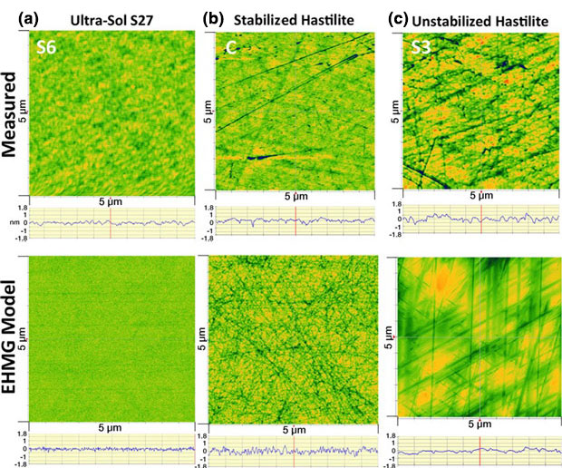
Ensemble Hertzian Multi-Gap Model.1,4 Here, a comprehensive set of glass samples (fused silica, phosphate, and borosilicate) were polished using various slurry particle-size distributions, slurry concentrations, and pad treatments; workpiece roughness and removal rate were subsequently measured. Using the EHMG model, based on multiple Hertzian contacts of slurry particles at the workpiece–pad interface in which the pad deflection and the effective interface gap at each pad asperity height are determined, a platform was developed to understand the microscopic interface interactions and to predict trends of the removal rate and surface roughness for a variety of polishing parameters. Using this platform, the interface contact area and each particle’s penetration, load, and contact zone were determined, which were used to calculate the material removal rate and simulate the surface roughness. Each of the key polishing variables investigated was shown to affect the material removal rate, whose changes were dominated by very different microscopic interactions. Slurry particle-size distribution affects the load per particle distribution and the fraction of particles removing material by plastic removal. The slurry concentration affects the areal number density of particles and fraction of load on particles versus pad. The pad topography affects the fraction of pad area making contact with the workpiece. The glass composition predominantly affects the depth of plastic removal. Also, the results showed that the dominant factor controlling surface roughness is the slurry particle-size distribution followed by the glass material’s removal function and the pad topography. The model compares well with the experimental data over a variety of polishing conditions for both removal rate and roughness (Figure 4). Also, the model can be extended to provide insights and strategies to develop practical, economic processes for obtaining ultra-low roughness surfaces while simultaneously maintaining high material removal rates.
IDG Model.5 In this part of this study, the polishing slurry pH and the generation of glass removal products are shown to influence the slurry particle spatial and height distribution at the polishing interface and the resulting roughness of the glass workpiece. The atomic force microscopy roughness was largely invariant with pH, suggesting the removal function of a single particle is unchanged with pH. However, the microroughness changed significantly, increasing linearly with pH for phosphate glass and having a maximum at an intermediate pH for fused silica. In addition, the spatial and height distribution of slurry particles the on the pad (as measured by laser confocal microscopy) was determined to be distinctly different at low and high pH during phosphate glass polishing. The zeta potential as a function of pH was measured for the workpiece, slurry and pad with and without surrogate glass products (K3PO4 for phosphate glass and Si(OH)4 for silica). The addition of K3PO4 significantly raised the zeta potential, while addition of Si(OH)4 had little effect on the zeta potential. An electrostatic DLVO 3-body force model, using the measured zeta potentials, was used to calculate the particle–particle, particle–workpiece, and particle–pad attractive and repulsive forces as a function of pH and the incorporation of glass products at the interface. The model predicted an increase in particle-–pad attraction with increase in pH and phosphate glass products consistent with the measured slurry distribution on the pads during phosphate glass polishing. Finally, a slurry "island" distribution gap (IDG) model has been formulated which utilizes the measured interface slurry distributions and a load balance to determine the interface gap, the contact area fraction, and the load on each slurry island. The IDG model was then used to simulate the workpiece surface topography and μ-roughness; the results showed an increase in roughness with pH similar to that observed experimentally.
4. Roughness and Redeposition
For the final major task, the focus was to determine the propensity of slurry particles to deposit on the workpiece surface as function of slurry chemical properties and workpiece roughness. Particle adsorption was explored in a model polishing system, consisting of silica colloids and like-charged silica surfaces. Using a quartz crystal microbalance with dissipation monitoring (QCM-D), the adsorption was monitored in situ under various suspension conditions and in the absence of surfactants or organic modifiers. Adsorption changes with particle concentration, particle size, pH, ionic strength and ionic composition were quantified by QCM-D and further characterized ex situ by atomic force microscopy. Transitions from near-zero adsorption to measurable adsorption were compared with predictions made using the DLVO theory. In addition, the impact of silica surface roughness on the propensity for particle adsorption was studied on various length scales by intentionally roughening the QCM sensor surface. It was found that the a change in silica surface roughness from 1.2 nm (rms) to 2.7 nm (rms) resulted in an increase in silica particle adsorption of 5-fold for 50-nm diameter particles and 1.5-fold for 100-nm diameter particles—far exceeding coverage levels achievable by altering solution conditions alone. These sets of electrostatic interactions provide insight to the adhesion of particles both during polishing and during post-cleaning processes.
Impact on Mission
The scientific understanding developed from this study paves the way to the development of improved, low-cost finishing processes for optics used in support of Laboratory missions in stockpile stewardship and laser science. Through the Laboratory's technology transfer program, the process strategies developed are being transferred to industry for making high-value, fusion-laser optics with lower roughness, which will lead to lower scatter and laser beam contrast. For example, these strategies have been incorporated into a previously developed finishing process called convergent polishing, which will yield both economical finishing process with improved surface figure control and low-roughness surfaces with high removal rates. Convergent polishing is currently at the pilot production stage for fabricating NIF optics. Additionally, this study has resulted in a series of peer-reviewed journal publications, which have been of high interest to those in the fields of optical fabrication, chemical-mechanical polishing, and laser science (see references).
Conclusion
We have developed a detailed understanding of the chemical and mechanical microscopic interactions that occur during polishing that affect the resulting surface microroughness of the workpiece. As a result, novel strategies to polish the workpiece have been developed that result in both ultrasmooth surfaces and high material removal rates. For example, these strategies have been incorporated into a previously developed finishing process called convergent polishing, which is in the pilot stage of finishing optics for NIF, and will be transferred to optical fabricators of NIF optics in the private sector.
References
- Suratwala, T. I., et al., “Chemistry and formation of the Beilby layer during polishing of fused silica glass surfaces.” J. Am. Ceram. Soc. 98(8), 2395 (2015). LLNL-JRNL-666384.
- Suratwala, T. I., et al., "Mechanism and simulation of removal rate and surface roughness during optical polishing of glasses." J. Am. Ceram. Soc. 99(6), 1974 (2016). LLNL-JRNL-715680.
- Shen, N., et al., "Nanoscratching of optical glass surfaces near the elastic–plastic load boundary to mimic the mechanics of polishing particles." J. Am. Ceram. Soc. 99(5), 1477 (2016). LLNL-JRNL-673669.
- Suratwala, T. I., et al., “Microscopic removal function and the relationship between slurry particle size distribution and workpiece roughness during pad polishing.” J. Am. Ceram. Soc. 97(1), 81 (2014). LLNL-JRNL-635673.
- Suratwala, T. I., et al. Relationship between surface μ-roughness and interface slurry particle spatial distribution during glass polishing. Lawrence Livermore National Laboratory (2016). LLNL-CONF-702699.
Publications and Presentations
- Dylla-Spears, R. J., et al., “Charged micelle halo mechanism for agglomeration reduction in metal oxide particle based polishing slurries.” Colloid. Surface. Physicochem. Eng. Aspect. 447, 32 (2014). LLNL-JRNL-644902. http://dx.doi.org/10.1016/j.colsurfa.2014.01.061
- Dylla-Spears, R., et al., “Adsorption of silica colloids onto like-charged silica surfaces of different roughness” Colloid. Surface. A: Physicochem. Eng. Aspect. 520, 85 (2017). LLNL-JRNL-707117. http://dx.doi.org/10.1016/j.colsurfa.2017.01.042
- Shen, N., et al., "Nanoscratching of optical glass surfaces near the elastic–plastic load boundary to mimic the mechanics of polishing particles." J. Am. Ceram. Soc. 99(5), 1477 (2016). LLNL-JRNL-673669. http://dx.doi.org/10.1111/jace.14083
- Suratwala, T. I., et al., “Convergent polishing: A simple, rapid, full aperture polishing process of high quality optical flats and spheres.” JoVE 94, 51965 (2014). LLNL-JRNL-648661. http://dx.doi.org/10.3791/51965
- Suratwala, T., et al., "Mechanism and simulation of removal rate and surface roughness during optical polishing of glasses." J. Am. Ceram. Soc. 99(6), 1974 (2016). LLNL-CONF-691577. http://dx.doi.org/10.1111/jace.14220
- Suratwala, T. I., et al., “Microscopic removal function and the relationship between slurry particle size distribution and workpiece roughness during pad polishing.” J. Am. Ceram. Soc. 97(1), 81 (2014). LLNL-JRNL-635673. http://dx.doi.org/10.1111/jace.12631
- Suratwala, T. I., et al., Relationship between surface μ-roughness and interface slurry particle spatial distribution during glass polishing. (2016). LLNL-CONF-702699.


